Urine receiver for gynecological nursing
A urine receiver, obstetrics and gynecology technology, applied in the directions of inoculation and ovulation diagnosis, chemical instruments and methods, medical science, etc., can solve the problems of the urine receiver not being able to take the middle urine for detection, and not being able to be reused.
- Summary
- Abstract
- Description
- Claims
- Application Information
AI Technical Summary
Problems solved by technology
Method used
Image
Examples
Embodiment 1
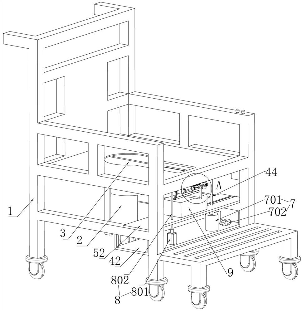
[0044]Embodiment 1, a urinal for obstetrics and gynecology care, including a seat 1 and a toilet 2. The bottom of the seat 1 is fixedly provided with a plurality of support legs, and the plurality of support legs are respectively rotatably mounted with universal wheels. The setting of the steering wheel can facilitate the movement of the seat 1. The seat 1 is provided with a toilet seat 3 above the toilet 2. The seat 1 is equipped with a soft material positioned around the toilet seat 3. The material can be selected such as sponge, which can provide a comfortable feeling for pregnant women. The seat 1 is placed with a toilet 2 below the toilet hole 3, and the lower end of the seat 1 is fixedly provided with a support plate, and a toilet is placed on the support plate. 2. It is convenient for pregnant women to sit on the seat 1. A drainage device 4 is slidably installed on the seat 1. When in use, the drainage device 4 provides drainage for urine. The drainage device 4 is detach...
Embodiment 2
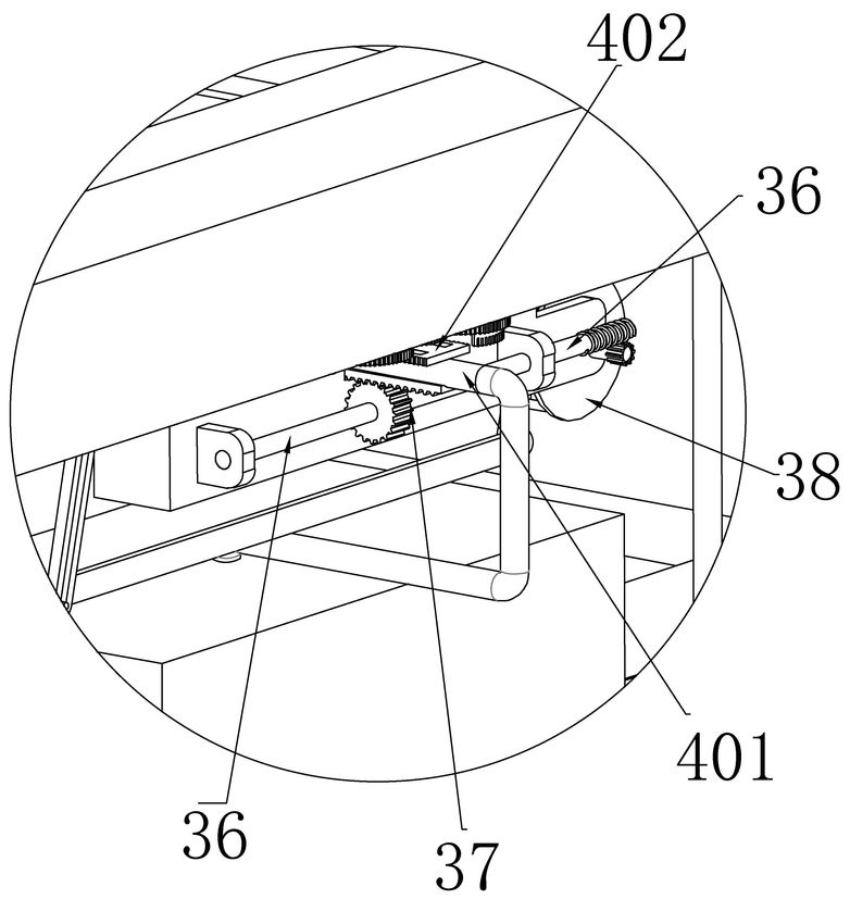
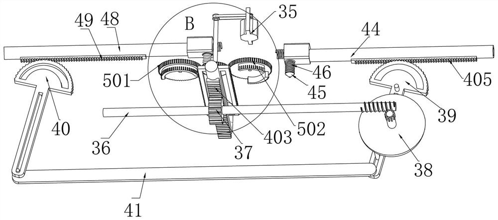
[0052] Embodiment 2. On the basis of Embodiment 1, the drainage device 4 is composed of a drainage tube 401, an upper rack 402 and a lower rack 403. The seat 1 is slidably installed in the left and right directions and is located above the toilet hole 3. The drainage tube 401, the drainage tube 401 can slide left and right on the seat 1, the upper end of the drainage tube 401 is fixedly installed with the upper rack 402, the front and rear sides of the upper rack 402 are respectively provided with teeth, so A lower rack 403 is fixedly installed at the lower end of the drainage tube 401 .
Embodiment 3
[0053] Embodiment 3, on the basis of Embodiment 2, the transmission device 5 is composed of a front gear 501 and a rear gear 502. The lower end of the seat 1 is rotatably equipped with a rotating rod 29, and the lower end of the seat 1 is rotatably installed. There are rear gears 501 and front gears 502 positioned at the front and rear sides of the rotating rod 29, and the rear gears 501 and the front gears 502 are respectively rotated and installed on the seat 1, and the lower end of the rotating rod 29 is coaxially fixedly installed with respectively The driven gear 34 meshed with the front gear 501 and the rear gear 502, the rotating rod 29 coaxially fixes the driven gear 34, the driven gear 34 is meshed with the rear gear 501 and the front gear 502 respectively, the driven gear The rotation of the gear 34 can drive the rear gear 501 and the front gear 502 to rotate respectively, and the bottom of the front gear 501 is fixedly equipped with a half gear 31 meshing with the fr...
PUM
 Abstract
Description
Claims
Application Information
 - R&D
- Intellectual Property
- Life Sciences
- Materials
- Tech Scout
- Unparalleled Data Quality
- Higher Quality Content
- 60% Fewer Hallucinations
Browse by: Latest US Patents, China's latest patents, Technical Efficacy Thesaurus, Application Domain, Technology Topic, Popular Technical Reports.
© 2025 PatSnap. All rights reserved.Legal|Privacy policy|Modern Slavery Act Transparency Statement|Sitemap|About US| Contact US: help@patsnap.com


