
Transformer area topological relation graph automatic drawing method based on multi-way tree layered layout

A topological relationship and automatic drawing technology, applied in image data processing, extraction from basic elements, 2D image generation, etc., can solve the problems of many nodes, long time, and high complexity

Pending Publication Date: 2020-10-23
INTEGRATED ELECTRONICS SYST LAB
View PDF0 Cites 4 Cited by
  • Summary
  • Abstract
  • Description
  • Claims
  • Application Information

AI Technical Summary

Problems solved by technology

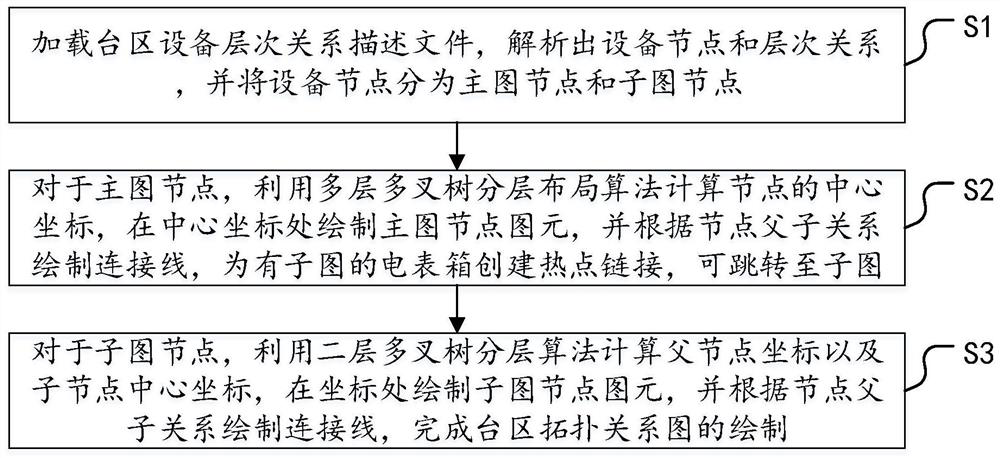
[0005] The purpose of the present invention is to provide a method for automatically drawing the topological relationship diagram of the station area based on the layered layout of the multi-fork tree, aiming at solving the problem of high complexity of the automatic diagramming algorithm in the prior art and the time-consuming problems caused by too many nodes, and realizing faster Drawing speed, improve work efficiency

Method used


Image

  • Transformer area topological relation graph automatic drawing method based on multi-way tree layered layout
  • Transformer area topological relation graph automatic drawing method based on multi-way tree layered layout
  • Transformer area topological relation graph automatic drawing method based on multi-way tree layered layout

Examples


Embodiment Construction

[0047] In order to clearly illustrate the technical features of the present solution, the present invention will be described in detail below through specific implementation methods and in conjunction with the accompanying drawings. The following disclosure provides many different embodiments or examples for implementing different structures of the present invention. To simplify the disclosure of the present invention, components and arrangements of specific examples are described below. Furthermore, the present invention may repeat reference numerals and / or letters in different instances. This repetition is for the purpose of simplicity and clarity and does not in itself indicate a relationship between the various embodiments and / or arrangements discussed. It should be noted that components illustrated in the figures are not necessarily drawn to scale. Descriptions of well-known components and processing techniques and processes are omitted herein to avoid unnecessarily lim...


PUM


Abstract

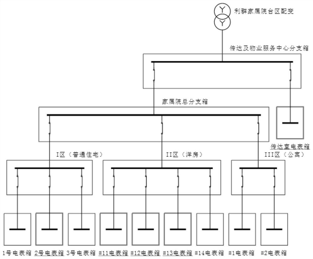
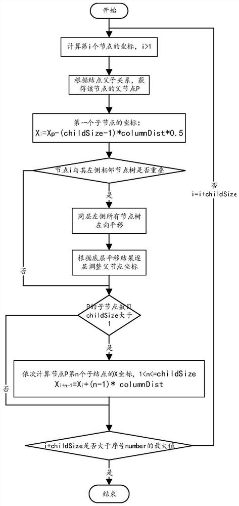
The invention provides a transformer area topological relation graph automatic drawing method based on multi-way tree layered layout, being characterized in that automatic layout is carried out by importing a topological file, so that manual drawing is not needed, and the working efficiency is high; coordinates of a main graph are calculated layer by layer, and the calculation complexity is reduced; an automatic mapping result is divided into a main graph and a plurality of sub-graphs, and the main graph and the sub-graphs can be carried out in parallel, and the mapping speed is high, and themain topology of the current transformer area can be presented more visually; when the automatic mapping result is not satisfactory, the manual adjustment can be realized, and the flexibility is higher; an automatic mapping result has no intersection of connecting lines and is clearer; and sub-graph electric energy meters are drawn in a split-phase mode, and inspectors can be helped to finely manage household meters.

Description

technical field [0001] The invention relates to the technical field of electric power system equipment management, in particular to a method for automatically drawing a topological relationship diagram of a station area based on a hierarchical layout of a multi-fork tree. Background technique [0002] In recent years, with the continuous advancement of the urbanization process, the number of residential quarters has increased rapidly, and the electricity demand of residents has increased. As of 2018, my country has installed a total of 554 million smart energy meters. Due to the characteristics of wide distribution, large number and low degree of automation of low-voltage power grid users, the level of automation and intelligent management of low-voltage distribution network is relatively backward compared with that of transmission network. The premise of improving the lean management level of the low-voltage station area is to be able to accurately obtain the topological r...

Claims


Application Information

Patent Timeline
Patent Type & Authority Applications(China)
IPC IPC(8): G06F30/18G06T11/20G06F113/04
CPCG06F30/18G06T11/206G06F2113/04
Inventor 宋先慧李尔园周文俊陈洪巧傅洋鞠永乾丁迁
Owner INTEGRATED ELECTRONICS SYST LAB
Learn More