Multi-bus and multi-channel interface realized in single serial port multiplexing mode
A multi-bus, single-serial-port technology, applied in instruments, electrical digital data processing, hardware monitoring, etc., can solve the problems of high cost, occupying printed circuit board area, occupying more than one serial communication port of the microcontroller, etc.
- Summary
- Abstract
- Description
- Claims
- Application Information
AI Technical Summary
Problems solved by technology
Method used
Image
Examples
Embodiment 1
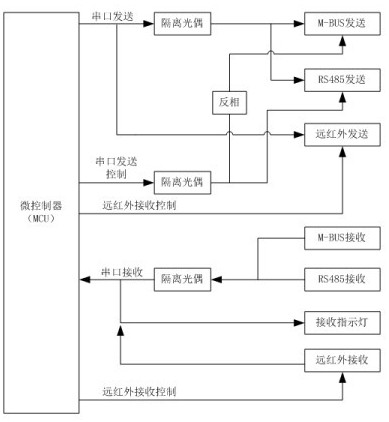
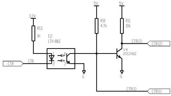
[0054] Such as Figure 1-7 As shown, the present invention includes an interface control circuit, a microcontroller serial port transmission / reception indicating circuit, an M_BUS bus transmission enable control circuit, an RS485 bus transmission / reception state control circuit, and a far-infrared IRD transmission / reception circuit; wherein the interface The control circuit includes an optocoupler E2 and a triode V4. The first pin of the optocoupler E2 (the anode of the light emitting tube) is connected to one end of the resistor R13, and the other end of the resistor R13 is connected to a 3.3V power supply; the second pin of the optocoupler E2 (the cathode of the light emitting tube ) is connected to the microcontroller IO pin CTR; the third pin of the optocoupler E2 (the emitter of the photoelectric receiver) is connected to the reference point G; the fourth pin of the optocoupler E2 (the collector of the photoelectric receiver) is connected to one end of the resistor R10 at ...
Embodiment 2
[0056] On the basis of Embodiment 1, the microcontroller serial port sending / receiving indication circuit includes an LED indicator HL1 and an LED indicator HL2;
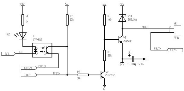
[0057] The microcontroller serial port sends an indicating circuit, the first pin of the optocoupler E1 (the anode of the light-emitting tube) is connected to the cathode of the LED indicator HL1, the anode of the LED indicator HL1 is connected to the resistor R1, and the other end of the resistor R1 is connected to the 3.3V power supply; The second pin of the optocoupler E1 (cathode of the light-emitting tube) is connected to the serial transmitter TXD of the microcontroller;
[0058] The micro-controller serial port receiving indication circuit, the third pin of the optocoupler E3 (photoelectric tube emitter) is connected to the GND reference ground; the fourth pin of the optocoupler E3 (photoelectric tube collector) is connected to the microcontroller serial receiving At the same time, the fourth pin of optocoupl...
Embodiment 3
[0061] On the basis of Embodiment 1, the M_BUS bus transmission enable control circuit is characterized in that it includes the control mode adopted by the optocoupler E1 and the third pin (photoelectric tube emitter) of the optocoupler E1; The three pins (photoelectric tube emitter) are connected to the collector CTR1 of the triode V4, the model of the optocoupler E1 is LTV-816S, and the model of the diode VD2 is 1N5819W.
PUM
| Property | Measurement | Unit |
|---|---|---|
| Resistance | aaaaa | aaaaa |
| Resistance | aaaaa | aaaaa |
| Resistance | aaaaa | aaaaa |
Abstract
Description
Claims
Application Information
 - R&D
- Intellectual Property
- Life Sciences
- Materials
- Tech Scout
- Unparalleled Data Quality
- Higher Quality Content
- 60% Fewer Hallucinations
Browse by: Latest US Patents, China's latest patents, Technical Efficacy Thesaurus, Application Domain, Technology Topic, Popular Technical Reports.
© 2025 PatSnap. All rights reserved.Legal|Privacy policy|Modern Slavery Act Transparency Statement|Sitemap|About US| Contact US: help@patsnap.com


