
Static pressure measuring structure for wall surface of flame tube, connecting device, combustion chamber and combustion chamber test system

A technology of connecting device and flame tube, which is applied in the field of measuring structure of static pressure on the wall of flame tube, can solve the problems such as difficult to replace, need to wait on site, increase the risk of assembly, etc.

Active Publication Date: 2020-10-23
AECC COMML AIRCRAFT ENGINE CO LTD
View PDF12 Cites 5 Cited by
  • Summary
  • Abstract
  • Description
  • Claims
  • Application Information

AI Technical Summary

Problems solved by technology

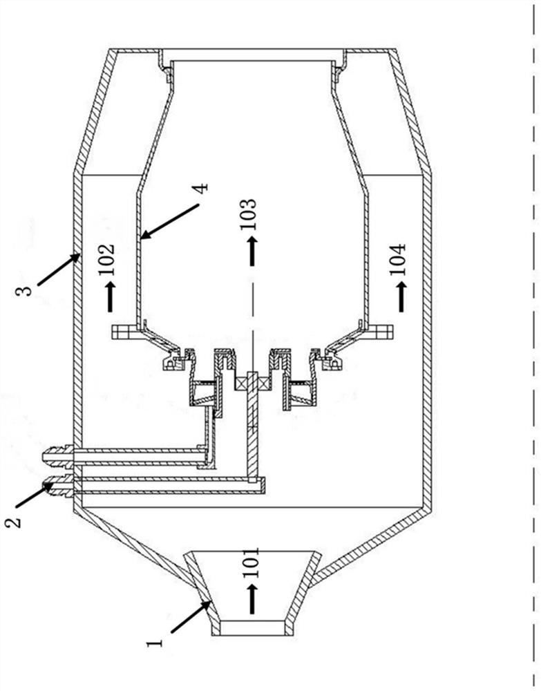
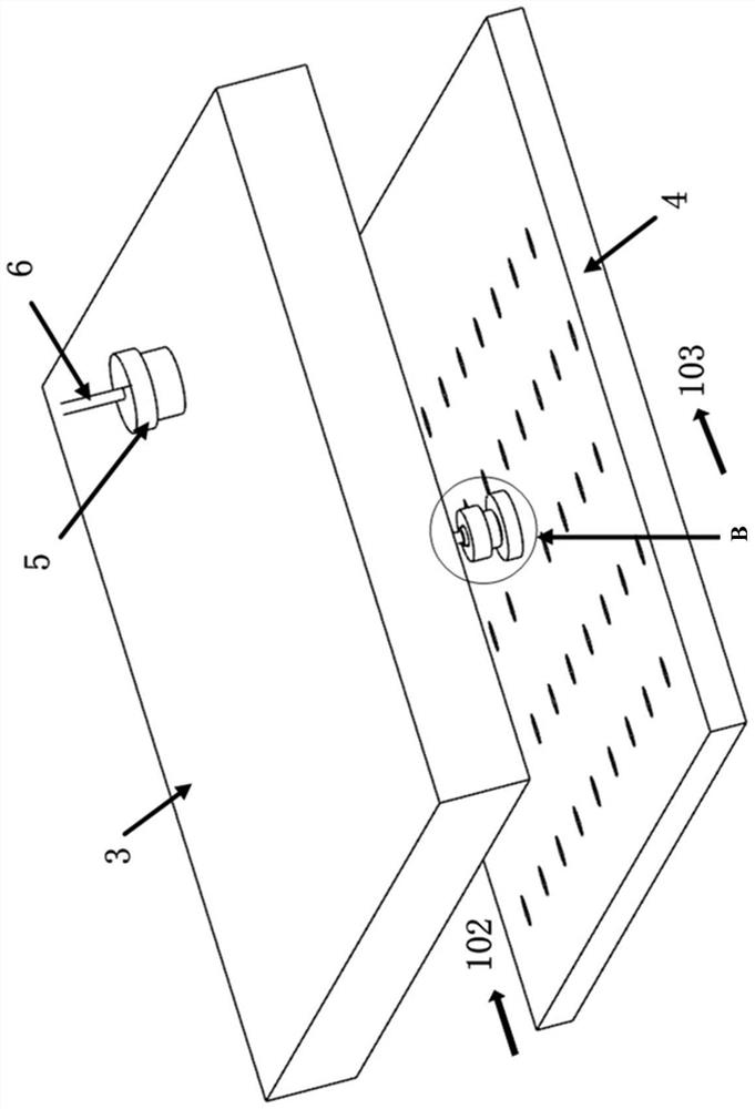
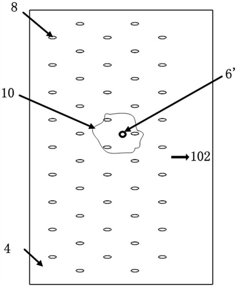
[0004] However, the inventors of the present invention have found in practice that due to the denser air film holes provided on the flame cylinder, the welding rods are also relatively thick during manual high-temperature brazing, and the solder is not easy to control, often resulting in at least three or more The plugging of the cooling holes 8, such as image 3 As shown, the installation hole is opened at the position avoiding the gas film hole, and the static pressure tube 6' is welded on the wall surface 4 of the flame tube through the static pressure lead hole, but the area of ​​solder accumulation is often as shown in area 10, or even more Large, it may cause local hot spots in the flame tube, which increases the risk of ablation of the flame tube. At the same time, it also increases the risk of failure of the static pressure tube due to high temperature. Often during the test, the static pressure tube is easily damaged. If it is welded, it is not easy to replace after it is broken. When replacing it, it needs to be welded again to cause damage to the flame tube; because the flame tube is a thin-walled part, it is easy to cause deformation of the flame tube during high-temperature brazing, which increases the risk of assembly; In addition, at present, the high-temperature brazing of the static pressure pipe on the wall of the flame tube can only be carried out manually on site, and the time for assembly and test wiring needs to be coordinated, but often the test wiring party needs to wait on site, resulting in waste of labor costs

Method used


Image

  • Static pressure measuring structure for wall surface of flame tube, connecting device, combustion chamber and combustion chamber test system
  • Static pressure measuring structure for wall surface of flame tube, connecting device, combustion chamber and combustion chamber test system
  • Static pressure measuring structure for wall surface of flame tube, connecting device, combustion chamber and combustion chamber test system

Examples


Embodiment Construction

[0034] The following discloses a variety of different implementations or examples for implementing the described subject technical solutions. In order to simplify the disclosure, specific examples of various elements and arrangements are described below, which are, of course, only examples and are not intended to limit the scope of protection of the present invention.

[0035] In addition, it should be understood that the orientation or positional relationship indicated by orientation words such as "front, rear, top, bottom, left, right", "horizontal, vertical, vertical, horizontal" and "top, bottom" and the like are usually Based on the orientation or positional relationship shown in the drawings, it is only for the convenience of describing the present invention and simplifying the description, and these orientation words do not indicate or imply that the indicated device or element must have a specific orientation unless otherwise stated. Or be constructed and operated in a...


PUM


Abstract

The invention relates to a static pressure measuring structure for the wall surface of a flame tube, a combustion chamber, a combustion chamber test system and a connecting device. The static pressuremeasuring structure comprises: a flame tube wall surface, which comprises a plurality of cooling holes and mounting holes located among the plurality of cooling holes; a static pressure tube; and theconnecting device, which is detachably connected with the flame tube wall surface through the mounting holes and is provided with a first channel, wherein one end of the first channel is connected with the static pressure tube, and the other end of the first channel is provided with an opening so as to allow the flame tube to communicate with the static pressure tube.

Description

technical field [0001] The invention relates to a measuring structure, a connecting device, a combustion chamber and a combustion chamber test system for the static pressure of the wall of a flame tube. Background technique [0002] In the development of the combustion chamber, the combustion chamber test is particularly important. During the combustion chamber test, the measurement of the static pressure on the wall of the combustion chamber flame tube can be used to approximate the total pressure at the outlet of the combustion chamber to calculate the total pressure loss of the combustion chamber, to calculate the flow rate of the fuel nozzle, to monitor the coking condition of the fuel nozzle, etc. The measurement of the static pressure on the wall of the chamber flame tube is very important for the combustion chamber test. However, the combustion chamber test is different from the general flow heat transfer test. Similar criteria cannot be used to replace the low tempe...

Claims


Application Information

Patent Timeline
IPC IPC(8): G01M15/02G01M15/04G01M15/09
CPCG01M15/02G01M15/04G01M15/09
Inventor 冯晓星王嘉平田晨
Owner AECC COMML AIRCRAFT ENGINE CO LTD
Learn More