
Combined multi-stage energy saver of equipment for recycling residual steam of waste water and waste heat

An energy-saving, combined technology, applied in heat exchange equipment, heat recovery systems, lighting and heating equipment, etc., can solve the problems of difficulty in using waste heat and waste steam at the same time, low recovery efficiency, etc.

Pending Publication Date: 2020-10-23
王国兴 +1
View PDF0 Cites 2 Cited by
  • Summary
  • Abstract
  • Description
  • Claims
  • Application Information

AI Technical Summary

Problems solved by technology

Existing recycling equipment has low recycling efficiency, and the residual steam is directly discharged into the atmosphere while still containing a lot of heat energy; it is difficult to use the waste heat and residual steam generated on the production line at the same time

Method used


Image

  • Combined multi-stage energy saver of equipment for recycling residual steam of waste water and waste heat
  • Combined multi-stage energy saver of equipment for recycling residual steam of waste water and waste heat
  • Combined multi-stage energy saver of equipment for recycling residual steam of waste water and waste heat

Examples


Embodiment 1

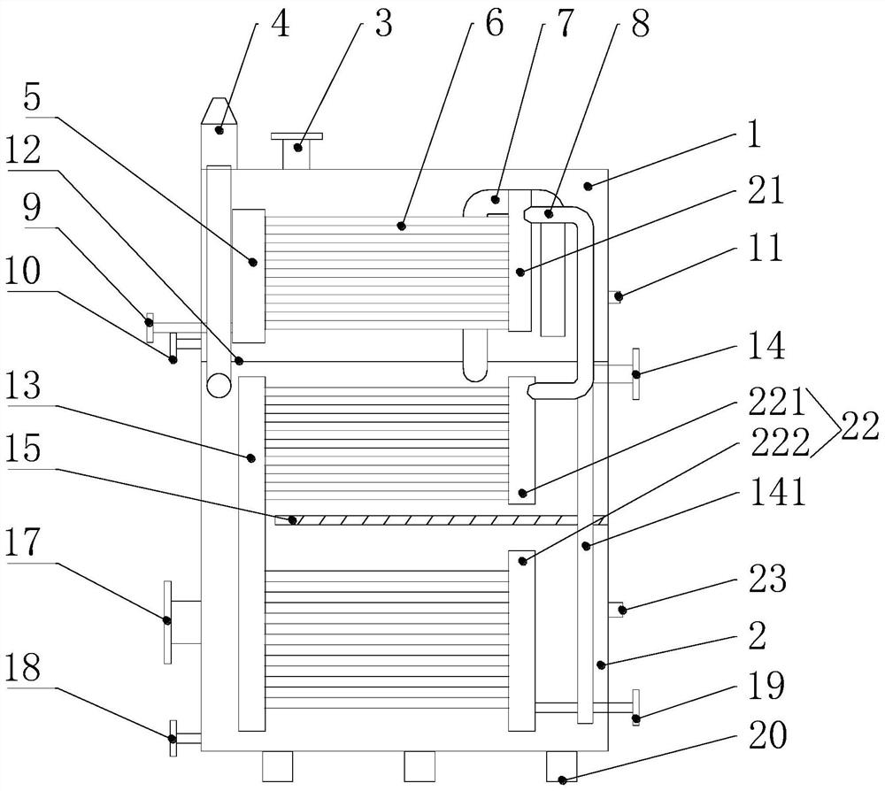
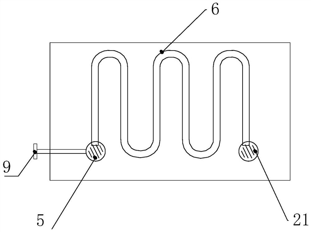
[0027] See figure 1 , the present invention has energy concentrator 1, economizer 2, and energy concentrator 1 and economizer 2 are box structures, and energy concentrator 1 is installed on the top of economizer 2, separates with clamping plate 12. The energy concentrator 1 is equipped with a first header 5, a second header 21, a serpentine pipe 6, a tank diversion pipe 7, and a waste heat diversion pipe 8, and an energy storage energy inlet device 3 and a condensate discharge pipe are arranged outside Seat 9, one end of the serpentine tube 6 is connected to the first header 5, the other end is connected to the second header 21, one end of the tank guide pipe 7 is connected to the interior of the economizer 2, and the other end is connected to the interior of the energy concentrator 1, and the condensed water The discharge pipe seat 9 communicates with the first header 5, and the storage energy inlet device 3 is installed on the top of the concentrator 1 and communicates with ...

Embodiment 2

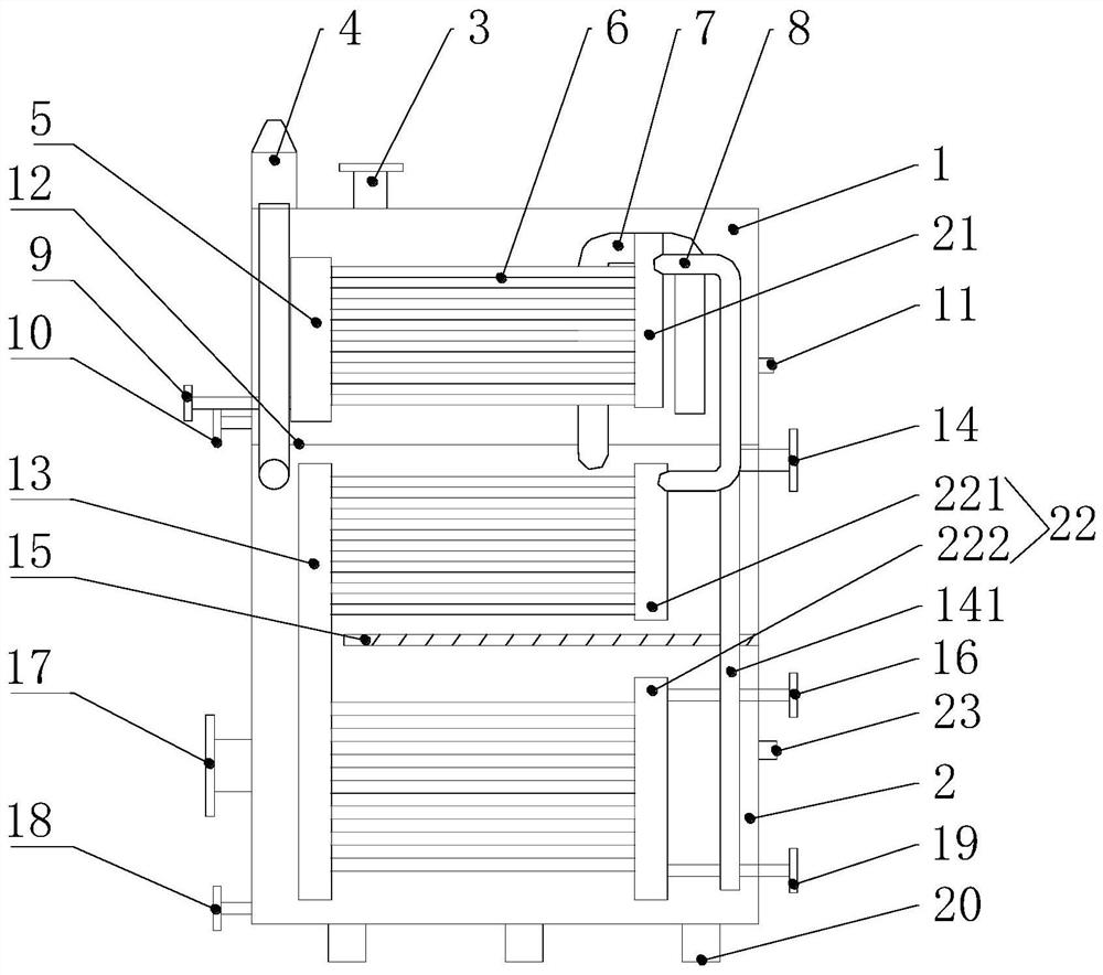
[0041] See figure 2 , this embodiment is basically the same as Embodiment 1, and its distinguishing feature is that: a waste heat source inlet socket 16 is also provided on the side wall of the economizer 2, and the waste heat source inlet socket 16 communicates with the right header 22. Two different heat sources can be recovered at the same time through the waste heat source inlet pipe socket 16 and the residual steam inlet pipe socket 19, which is fast and efficient.

[0042] working principle:

[0043] According to the actual waste heat conditions of different customers, one or more residual steam inlet sockets 19 are provided, or the waste heat source inlet sockets 16 and the residual steam inlet sockets 19 can be used together. The storage energy enters the box body of the concentrator 1 from the energy storage energy inlet device 3 , flows into the box body of the economizer 2 through the box guide pipe 7 , bypasses the clip guide plate 15 , and finally exits the storag...


PUM


Abstract

The invention relates to the field of waste water and waste heat recycling, in particular to equipment for recycling residual steam of waste water and waste heat. The equipment is provided with an energy collector and an energy saver, wherein the energy collector and the energy saver are both of a box body structure; the energy collector is installed on the upper part of the energy saver and separated from the energy saver by a bin clamping plate; a first header, a second header, a snakelike pipe, a box body guide pipe and a waste heat guide pipe are arranged in the energy collector; an energystorage inlet device and a condensed water discharge pipe seat are arranged outside the energy collector; a left header, a right header and a snakelike pipe are arranged in the energy saver; and an energy storage discharge device and a residual steam inlet pipe seat are arranged outside the energy saver. The equipment for recycling the residual steam of the waste water and the waste heat has theadvantages of compact structure, convenient operation, smooth running of the residual steam of the waste heat, reverse movement of the energy storage and the residual steam of the waste heat, scientific heat exchange process principle, and high utilization efficiency; and the equipment has a three-stage heat exchange process to ensure the maximum utilization of the residual steam of the waste heat, and a large temperature difference between the energy storage and waste heat is always kept in the three-stage heat exchange process, so that the heat value utilization rate is fully improved, and the heat exchange efficiency is high.

Description

technical field [0001] The invention relates to the field of recovery and reuse of waste heat and waste water, in particular to a combined multi-stage energy-saving device for recovery and utilization of waste heat and steam from waste water. Background technique [0002] The existing printing and dyeing industry and building materials industry such as: printing and dyeing, concrete pipe piles, aerated lime sand bricks, and aerated concrete block production lines consume about 16% of the production cost of heat. Therefore, enterprises have improved the fuel structure and adopted natural gas, light diesel oil, etc., resulting in high fuel costs. For the sake of protecting the ecological environment, it is of great practical significance to recycle the high-calorie waste heat, residual steam, and waste water discharged from the production line. The recovery efficiency of existing recycling equipment is low, and the residual steam is directly discharged into the atmosphere whi...

Claims


Application Information

Patent Timeline
Patent Type & Authority Applications(China)
IPC IPC(8): F28D21/00F28F17/00F28F27/00
CPCF28D21/0001F28F17/005F28F27/00Y02B30/56
Inventor 王国兴曹玉
Owner 王国兴
Learn More