Heat pipe type soil treatment device

A soil treatment and heat pipe technology, applied in the field of heat pipes, can solve the problems of failure to save energy

Inactive Publication Date: 2020-10-23
SHANDONG UNIV
View PDF7 Cites 0 Cited by
  • Summary
  • Abstract
  • Description
  • Claims
  • Application Information

AI Technical Summary

Problems solved by technology

However, there are deficiencies in this scheme: on the one hand, it does not achieve energy conservation, and on the other hand, it is restricted by more geographical restrictions and natural conditions.

Method used


Image

  • Heat pipe type soil treatment device
  • Heat pipe type soil treatment device
  • Heat pipe type soil treatment device

Examples


Embodiment Construction

[0045] The specific embodiments of the present invention will be described in detail below in conjunction with the accompanying drawings.

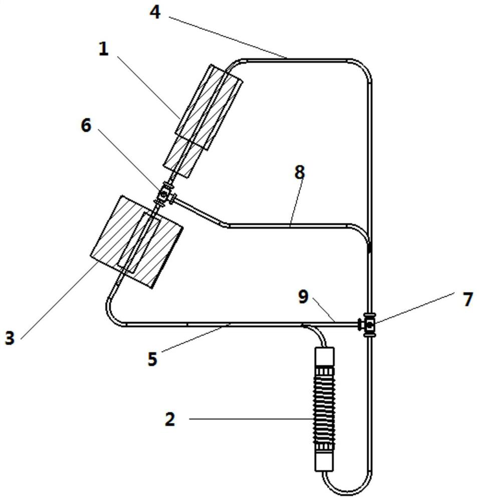
[0046] Such as figure 1 As shown, a loop heat pipe includes an evaporator 1, a condenser 2 and a heat accumulator 3, and the evaporator 1 and the condenser 2 form a circulation pipeline through a first pipeline 4 and a second pipeline 5, so The fluid absorbs heat and evaporates in the evaporator, then enters the condenser 2 to release heat through the first pipeline 5, and then circulates the fluid from the condenser 2 back to the evaporator 1 through the second pipeline 5, and the heat accumulator 3 Set in the second line. By setting the heat accumulator, excess heat can be stored in the heat accumulator, so as to better realize the utilization of heat.

[0047]Preferably, the heat pipe further includes a first three-way valve 7 and a second three-way valve 6, the first three-way valve 7 is set on the first pipeline 4, and the second th...


PUM


Abstract

The invention provides a soil treatment device. The soil treatment device comprises a heat pipe, wherein the heat pipe comprises an evaporator and a condenser, the condenser is arranged in soil, the condenser is of a coil pipe structure arranged on a plane, and hot fluid in the condenser flows from the outside to the center and dissipates heat to the soil. In the radial direction along the centerof a circular structure, the distribution density of coils increases. The main reason is that by this arrangement, it is possible to cause heat to dissipate initially from the outer end of the circular structure and then gradually inwards. Due to the fact that the pipe diameter of the coil pipe at the outer end is large, more heat is needed, the integral heat dissipation is uniform, the soil restoration effect is enhanced, and the integral restoration is uniform.

Description

technical field [0001] The invention belongs to the field of heat pipes, in particular to a loop heat pipe. Background technique [0002] Heat pipe technology is a heat transfer element called "heat pipe" invented by George Grover of Los Alamos National Laboratory in the United States in 1963. It makes full use of the principle of heat conduction and phase change medium. The rapid heat transfer properties of the heat pipe quickly transfer the heat of the heating object to the heat source, and its thermal conductivity exceeds that of any known metal. [0003] Heat pipe technology was widely used in aerospace, military and other industries before. Since it was introduced into the radiator manufacturing industry, people have changed the traditional radiator design ideas and got rid of the single heat dissipation mode that only relies on high air volume motors to obtain better heat dissipation. The use of heat pipe technology enables the radiator to obtain a satisfactory heat e...

Claims


Application Information

Patent Timeline
Patent Type & Authority Applications(China)
IPC IPC(8): F28D15/02F28D15/04F28D15/06F28D20/02F24S10/95F24S20/40F24S23/30B09C1/06
CPCB09C1/06B09C2101/00F28D15/0266F28D15/046F28D15/06F28D20/02F24S10/95F24S20/40F24S23/30Y02E10/44Y02E60/14
Inventor 郭春生江程李佳航姜鲲辛稀龙徐怡平纪文睿张欣哲张茜卓
Owner SHANDONG UNIV
Why Eureka
Try Eureka