
High-dynamic high-frequency response control system of electromagnetic valve and method thereof

A technology of control system and control method, applied in the direction of valve details, valve devices, engine components, etc., which can solve the problems of shortening cycle time, non-optimization, etc.

Pending Publication Date: 2020-10-23
ZHEJIANG UNIV OF TECH
View PDF1 Cites 1 Cited by
  • Summary
  • Abstract
  • Description
  • Claims
  • Application Information

AI Technical Summary

Problems solved by technology

[0006] However, the existing 3-voltage source control (patent [CN201610015304.4]) method only divides one cycle into four stages to achieve the effect of shortening the cycle time and increasing the operating frequency of the solenoid valve, but it does not go further for each stage Optimization

Method used


Image

  • High-dynamic high-frequency response control system of electromagnetic valve and method thereof
  • High-dynamic high-frequency response control system of electromagnetic valve and method thereof
  • High-dynamic high-frequency response control system of electromagnetic valve and method thereof

Examples


Embodiment Construction

[0040] The present invention will be further described below in conjunction with the accompanying drawings and specific embodiments.

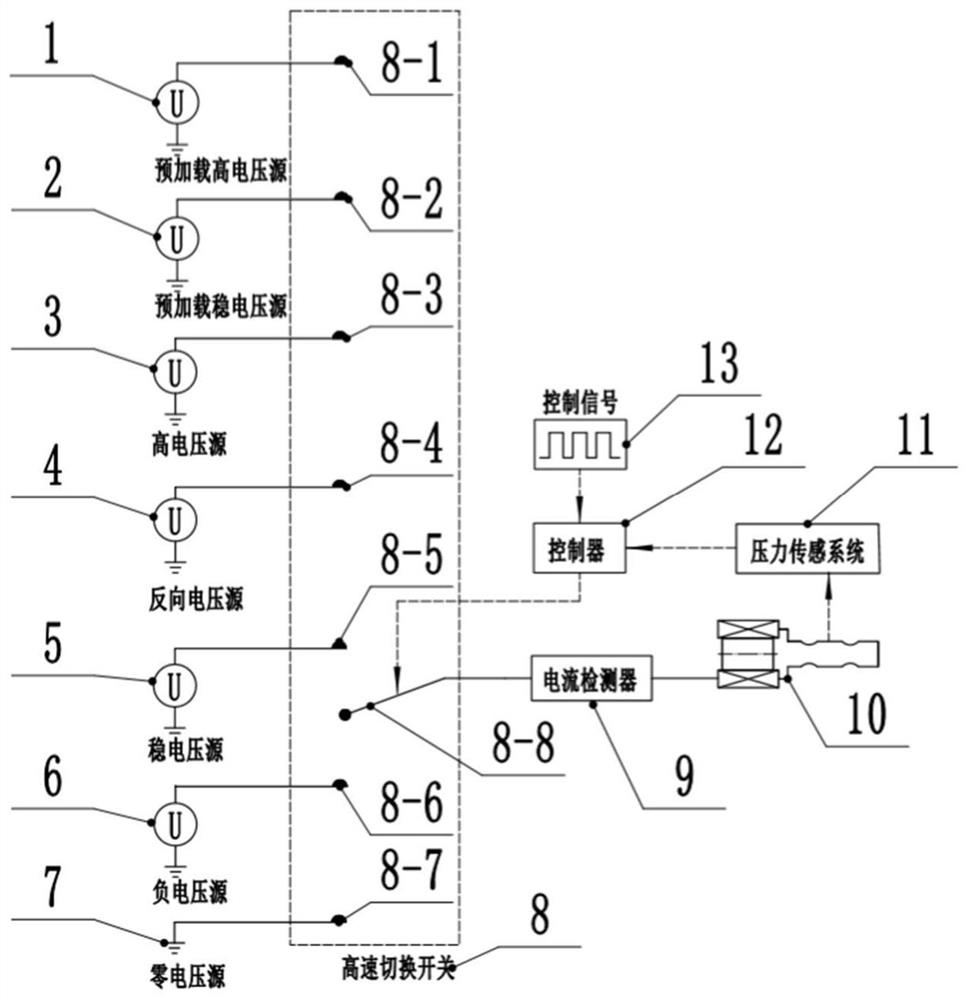
[0041] Such as figure 1 As shown, the system of this embodiment includes a preload high voltage source (1), a preload stabilized voltage source (2), a high voltage source (3), a reverse voltage source (4), a stabilized voltage source (5), a negative Voltage source (6), zero voltage source (7), high-speed switch (8), current detector (9), solenoid valve (10), pressure sensing system (11) and controller (12);

[0042] Wherein, the controller 12 includes a control signal generating unit, the control signal 13 is generated by the operator through programming of the control signal generating unit inside the controller, and the control signal participates in the internal calculation of the controller. The controller 11 acquires the duty ratio, frequency, rising edge time and falling edge time of the control signal generated by the control signal gen...


PUM


Abstract

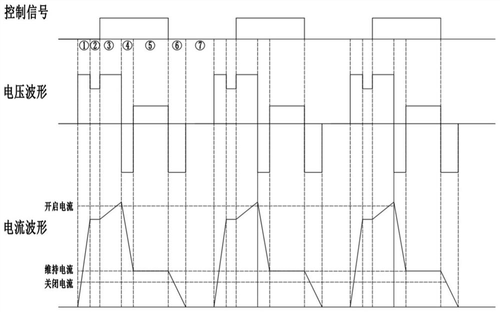
The invention discloses a high-dynamic high-frequency response control system of an electromagnetic valve and a method thereof. The system comprises a preloaded high voltage source, a preloaded stablevoltage source, a high voltage source, a reverse voltage source, a stable voltage source, a negative voltage source, a zero voltage source, a high-speed switching switch, a current detector, the electromagnetic valve, a pressure sensing system and a controller. The pre-loaded high voltage source is loaded in advance before the expected opening and closing time of the electromagnetic valve, and acoil current is kept in a state slightly smaller than an opening current through the pre-loaded stable voltage source. In the opening stage, the high voltage source is adopted for excitation, so thatthe current rises rapidly, and the motion time in the opening stage is shortened; the reverse voltage source is adopted for excitation before the maintaining stage, so that the coil current is rapidlyreduced from the opening current to a maintaining current; and in the closing stage, the negative voltage source is adopted for excitation, so that the current rapidly drops to zero, and the motion time in the closing stage is shortened.

Description

technical field [0001] The invention relates to the field of solenoid valve control, in particular to a high-dynamic and high-response control system and method for a solenoid valve. Background technique [0002] In the solenoid valve, the number of ampere turns and the working air gap have the greatest influence on the electromagnetic force of the electromagnet. Ampere-turns is the product of the number of turns of the coil and the current in the single-turn coil. When the magnetic flux is not saturated, the greater the current, the greater the electromagnetic force; the smaller the working air gap, the greater the electromagnetic force. Since the solenoid valve is often opened when the working air gap in the electromagnet is the largest, and when it is closed is often the time when the working air gap in the electromagnet is the smallest, so the opening current is larger than the closing current. [0003] At present, most hydraulic solenoid valves adopt a single-voltage ...

Claims


Application Information

Patent Timeline
IPC IPC(8): F16K31/06
CPCF16K31/0675
Inventor 钟麒孙造诣何贤剑王军汪谢乐李研彪陈波孙鹏
Owner ZHEJIANG UNIV OF TECH
Learn More