
Large-angle swing floor spring

A floor spring and large-angle technology, applied in the field of large-angle swing floor springs, can solve problems such as collision interference, ground spring design without consideration of ±180 degrees, damage, etc.

Inactive Publication Date: 2020-10-23
杭州银湖机械弹簧有限公司
View PDF0 Cites 1 Cited by
  • Summary
  • Abstract
  • Description
  • Claims
  • Application Information

AI Technical Summary

Problems solved by technology

[0005] First, the design of the floor spring itself does not consider reaching ±180 degrees.
[0006] Second, because the door frame has a certain thickness, when the door is opened to close to ±180 degrees, the door will collide with the door frame, and the door frame will limit the opening of the door
[0008] First, after the door is opened, whether it is opened inward or outward, it needs to occupy a certain amount of space
[0009] Second, for doors close to the street, after opening, there are certain safety hazards for passing pedestrians and vehicles, and it is easy to hurt passing pedestrians or vehicles, and the door will also be damaged after being hit.

Method used


Image

  • Large-angle swing floor spring
  • Large-angle swing floor spring
  • Large-angle swing floor spring

Examples


Embodiment Construction

[0058] The specific implementation manners of the present invention will be further described in detail below in conjunction with the accompanying drawings and embodiments. The following examples or drawings are used to illustrate the present invention, but not to limit the scope of the present invention.

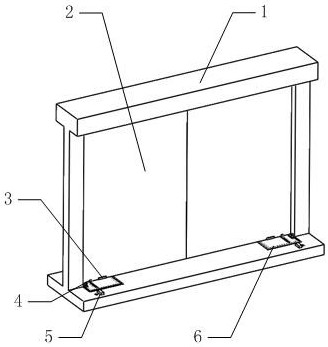
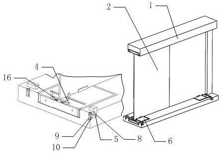
[0059] Such as figure 1 As shown, it includes a door frame 1 and a glass door 2, wherein two glass doors 2 are installed symmetrically on the door frame 1, and is characterized in that: Figure 4 As shown, the upper and lower ends of each glass door 2 are installed on the door frame 1 through the upper installation module 14 and the lower installation module 6; when the glass door 2 is swinging open, the upper installation module 14 and the lower installation module 6 can Make the glass door 2 slide relative to the door frame 1 in the direction of swinging open.

[0060] Such as Figure 6 , 7 As shown, the above-mentioned upper mounting module 14 includes a mounting she...


PUM


Abstract

The invention relates to the technical field of glass door floor spring, in particular to a large-angle swing floor spring. The floor spring comprises a door frame and a glass door. After the glass door is opened 180 degrees, due to the inertia of the swing of the glass door, the glass door can hit the door frame or a wall, causing damage to the glass door. The floor spring designs a buffer block.The buffer block is used to offset the inertial force of the glass door to prevent the glass door from knocking down the door frame or the wall, causing damage to the glass door. By adjusting the length of a damping screw rod in a first guide groove and a second guide groove, the resistance in the sliding process of two pistons is determined, that is, by adjusting the damping screw rod, the resistance of the rotation of a cam can be adjusted, and then the resistance of the glass door in the process of opening and closing can be adjusted. The nested motion of a first sliding rod and a second sliding rod is designed, on the one hand, the installation space is reduced, and on the other hand, the motion stroke of a first return spring and a second return spring is reduced.

Description

[0001] Technical field [0002] The invention belongs to the technical field of floor springs for glass doors, and in particular relates to a large-angle swing floor spring. Background technique [0003] The floor spring is a hydraulic door closer, except that the device that compresses the spring is a cam instead of a rack and pinion. Because the cam can rotate forward and reverse, the floor spring can be used for doors that open in both directions. [0004] At present, the opening angle of the floor spring is about ±110 degrees instead of ±180 degrees; there are two main reasons for this: [0005] First, the design of the floor spring itself does not consider reaching ±180 degrees. [0006] Second, because the door frame has a certain thickness, after the door is opened to approximately ±180 degrees, the door will collide with the door frame and interfere, and the door frame restricts the opening of the door. [0007] Doors installed through existing floor springs have th...

Claims


Application Information

Patent Timeline
Patent Type & Authority Applications(China)
IPC IPC(8): E05F3/08E05F3/20E05F3/22E05F5/06E05D7/081E05D11/10
CPCE05D7/081E05D11/1028E05F3/08E05F3/20E05F3/22E05F5/06
Inventor 潘俐邵文宇董淑文
Owner 杭州银湖机械弹簧有限公司
Learn More