A high-speed, high-precision CNC edge folding machine and a method for solving the displacement of the edge folding beam

An edge folding machine, high-precision technology, applied in the direction of forming tools, instruments, manufacturing tools, etc., can solve the problems of difficult to guarantee machining accuracy, low efficiency, and influence of machining accuracy, and achieve intelligent control and simple kinematic inverse solution , precision and easy to control the effect

Active Publication Date: 2021-07-13
南京云上自动化科技有限公司
View PDF10 Cites 0 Cited by
  • Summary
  • Abstract
  • Description
  • Claims
  • Application Information

AI Technical Summary

Problems solved by technology

[0005] 1. The above-mentioned horizontal driving mechanism has additional swing while moving in the horizontal direction; the vertical driving mechanism also has additional swing while driving the vertical direction movement, so it cannot realize the two freedoms in the X and Y directions in the absolute sense. single translation of degrees
Therefore, the precise control of the tool nose trajectory cannot be realized, and the control accuracy is poor. When the angle correction is performed during the bending process, it can only be corrected by manually inputting the correction parameters many times, and the calculation of the correction value cannot be automatically completed through precise mathematical calculations. , low efficiency, and difficult to achieve intelligent control
In addition, due to the poor precision of the tool tip trajectory, the problem of leaving indentations on the board surface during the bending process is inevitable
[0006] 2. The processing accuracy of the equipment depends on the processing and assembly accuracy of each hinge point. Therefore, it is difficult to process and manufacture, and it is difficult to realize mass production, which limits its large-scale promotion
In addition, in CN201610497320.1, the hinge point is not only used for driving, but also guides the edge beam, or limits the degree of freedom
Therefore, the manufacturing error of the hinge point will affect the parallelism of the flange beam in the horizontal direction and the vertical direction during the movement.
[0007] 3. Due to the additional swing, it is difficult to realize the real-time feedback of the movement position of the hem beam (the feedback measurement sensor is nowhere to be installed), so it is difficult to realize the closed-loop feedback and control of the movement position of the hem beam, so the machining accuracy is difficult to guarantee
[0008] 4. The wear of the hinge points, the elastic deformation of each rod in the mechanism, and the temperature deformation of the components will have a great impact on the machining accuracy

Method used


Image

  • A high-speed, high-precision CNC edge folding machine and a method for solving the displacement of the edge folding beam
  • A high-speed, high-precision CNC edge folding machine and a method for solving the displacement of the edge folding beam
  • A high-speed, high-precision CNC edge folding machine and a method for solving the displacement of the edge folding beam

Examples


Embodiment 1

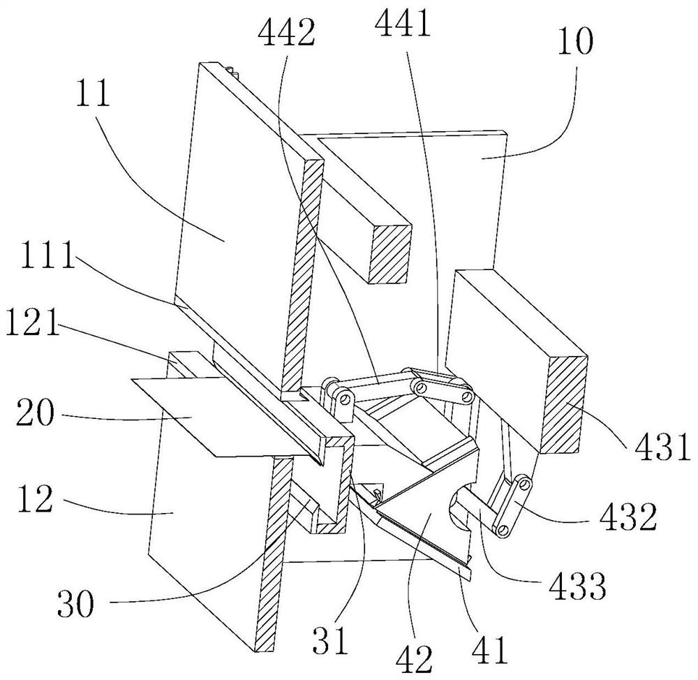
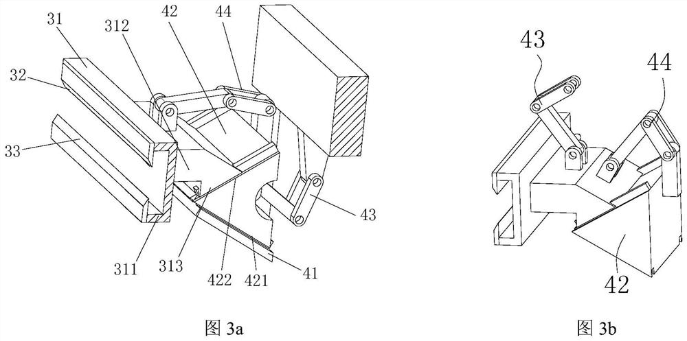
[0124] Example 1: as figure 1 and image 3 As shown in a, one end of connecting rod 1 is hinged with crank 1, and the other end of connecting rod 1 is hinged with driving seat.

Embodiment 2

[0125] Example 2: as figure 2 and image 3 As shown in b, one end of the connecting rod 1 is hinged with the crank 1, and the other end of the connecting rod 1 is hinged with the folding beam. In this embodiment, the kinematic inverse solution is simpler, and the sliding auxiliary load of the guide is smaller.

[0126] In the present invention, the connecting rod transmission of the first crank-link mechanism preferably has the following two driving modes.

[0127] Driving mode 1: A servo motor 1 is preferably arranged on the frame to drive the rotation of the crank 1.

[0128] Driving mode 2: The connecting rod transmission of the first crank connecting rod mechanism is driven by the toggle lever mechanism. The specific setting method is as follows: the toggle lever mechanism is hingedly installed at the hinge point where the crank 1 and the connecting rod 1 are hinged, and the hinge point is called the hinge point. Drive hinge point.

[0129] Wherein, the toggle mechani...

Embodiment 3

[0153] Embodiment 3, horizontal movement

[0154] Through the nonlinear coupling drive (compound drive) of the first crank drive mechanism and the second crank drive mechanism, the driving process is as follows Figure 7 As shown, the horizontal translation movement can be realized.

[0155] During the horizontal translation process, the displacement X and displacement Y of the folded beam can be solved analytically through the real-time readings of the two grating rulers. The displacement movement process of the two cursor rulers, such as Figure 9 a shown.

[0156] like Figure 10 As shown in the figure, a method for solving the displacement of the folded beam, the folded beam solves its own displacement through two sets of grating scales, and the specific solution method includes the following steps.

[0157] Step 1. Establish the coordinate system and the linear equation of the grating ruler, including the following steps.

[0158] Step 11. Establish a coordinate syst...


PUM


Abstract

The invention discloses a high-speed, high-precision numerical control folding machine and a method for solving the displacement of a folding beam, including a machine frame, a blanking beam, a folding die, a folding beam, an inclined slide rail, a driving seat, and a first crank connecting rod Mechanism and the second crank-link mechanism; the driving seat has intersecting slope one and slope two; slope one is slidably connected to the slope slide rail, and the slope slide rail is fixed on the frame; slope two slides with the folding beam of the edge folding machine Cooperate; one end of the first crank-link mechanism is fixed on the machine frame, and the other end is hinged with the driving seat or the flange beam; one end of the second crank-link mechanism is hinged with the drive seat, and the other end is hinged with the flange beam; The side beam realizes the displacement in the vertical direction and the horizontal direction under the common coupling action of the two crank-link mechanisms. The invention can realize translational movement in the horizontal direction and the vertical direction without additional swing, the control precision of the tool tip track is high, the appearance of the plate surface is smooth and clean during the bending process, and there is no indentation; the rigidity of the bending die is high, and the moving secondary load Small.

Description

technical field [0001] The invention relates to the field of sheet metal processing, in particular to a high-speed, high-precision numerical control folding machine and a method for solving the displacement of a folding beam. Background technique [0002] The folding machine is a simple bending machine, which can be manual or motorized. The folding machine is a mechanical device that processes the edge of the product. The existing traditional folding machine can only achieve a single up and down folding action, and cannot Realize complex hemming trajectories. With the development of social economy, people's needs for workpieces are getting wider and wider, and traditional folding machines cannot meet the needs of customers. In addition, the structure of the traditional folding machine is too simple, the transmission precision is low, and the product quality is poor. [0003] The Chinese invention patent application with the application number CN201610497320.1, the title of...

Claims


Application Information

Patent Timeline
Patent Type & Authority Patents(China)
IPC IPC(8): B21D19/08B21D37/12G01B11/03
CPCB21D19/08B21D37/12G01B11/03
Inventor 徐丰羽李剑
Owner 南京云上自动化科技有限公司
Why Eureka
Try Eureka