
Miniature array ultrasonic transducer, preparation method thereof, and ultrasonic probe including miniature array ultrasonic transducer

An ultrasonic transducer and microarray technology, which is applied in ultrasonic/acoustic/infrasonic diagnosis, ultrasonic diagnosis, infrasonic diagnosis, etc., can solve the problems of complex product structure and preparation process, poor ultrasonic imaging performance, etc.

Pending Publication Date: 2020-10-23
SUZHOU INST OF BIOMEDICAL ENG & TECH CHINESE ACADEMY OF SCI
View PDF0 Cites 4 Cited by
  • Summary
  • Abstract
  • Description
  • Claims
  • Application Information

AI Technical Summary

Problems solved by technology

[0005] Therefore, the technical problem to be solved by the present invention is to overcome the defects of existing ultrasonic transducers due to the existence of electrode connecting wires, which make the product structure and manufacturing process complicated and lead to poor ultrasonic imaging performance, thereby providing a microarray ultrasonic transducer device, the preparation method of the micro-ultrasonic transducer and the ultrasonic probe comprising the micro-array ultrasonic transducer

Method used


Image

  • Miniature array ultrasonic transducer, preparation method thereof, and ultrasonic probe including miniature array ultrasonic transducer
  • Miniature array ultrasonic transducer, preparation method thereof, and ultrasonic probe including miniature array ultrasonic transducer
  • Miniature array ultrasonic transducer, preparation method thereof, and ultrasonic probe including miniature array ultrasonic transducer

Examples


Embodiment 1

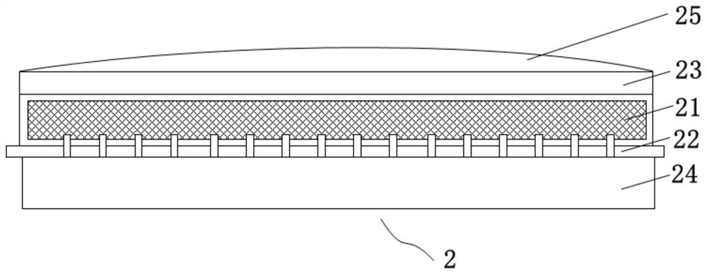
[0066] The present embodiment provides a microarray ultrasonic transducer 2, such as figure 2 As shown, it includes a piezoelectric wafer 21 , a flexible circuit board 22 , an acoustic matching layer 23 , a backing layer 24 and an acoustic lens layer 25 .

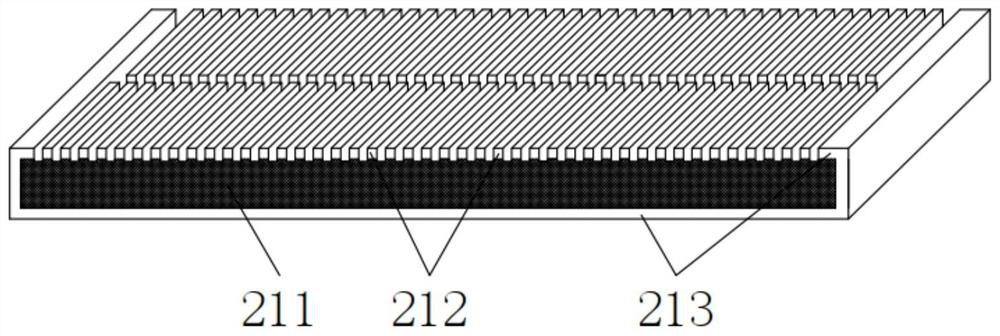
[0067] The piezoelectric chip 21 is the core component of the micro-array ultrasonic transducer 2. After receiving the voltage, it generates vibration and outputs ultrasonic waves. The parameters such as the shape, material, and thickness of the piezoelectric chip 21 directly affect the performance of the micro-array ultrasonic transducer 2. , which in turn determines the quality of ultrasound imaging. Such as image 3 As shown, the piezoelectric wafer 21 includes a piezoelectric material layer 211 , a first piezoelectric electrode 212 and a second piezoelectric electrode 213 .

[0068] The shape of the piezoelectric material layer 211 can be selected from geometric shapes such as rectangle, circle, and ellipse, and its ...

Embodiment 2

[0079] This embodiment provides a method for preparing the microarray ultrasonic transducer as described in Embodiment 1, such as Figure 8 shown, including the following steps:

[0080] The first step is to prepare a piezoelectric wafer with an edge wrapping structure

[0081] Continuous conductive sheets are arranged on both surfaces and part of the edges of the piezoelectric material layer 211 to form a piezoelectric wafer 21 with an edge wrapping structure. Specifically, on the upper and lower surfaces and two short sides of the rectangular 1-3 type piezoelectric composite material, a continuous conductive sheet is provided by evaporation, electrochemical deposition, magnetron sputtering, etc., and the conductive sheet only covers The two short sides and the two long sides of the piezoelectric material layer 211 are not provided with conductive sheets, that is, a piezoelectric chip 21 with a double-side wrapping structure is formed. In this embodiment, vapor deposition i...

Embodiment 3

[0096] This embodiment provides another preparation method of the microarray ultrasonic transducer as described in Embodiment 1, such as Figure 9 shown, including the following steps:

[0097] The first step is to prepare a piezoelectric wafer with an edge wrapping structure

[0098] Continuous conductive sheets are arranged on both surfaces and part of the edges of the piezoelectric material layer 211 to form an edge-wrapped piezoelectric wafer 21 . Specifically, on the upper and lower surfaces and two short sides of the rectangular 1-3 type piezoelectric composite material, a continuous conductive sheet is provided by evaporation, electrochemical deposition, magnetron sputtering, etc., and the conductive sheet only covers The two short sides and the two long sides of the piezoelectric material layer 211 are not provided with conductive sheets, that is, a piezoelectric chip 21 with a double-side wrapping structure is formed. In this embodiment, vapor deposition is used.

...


PUM

PropertyMeasurementUnit
Thicknessaaaaaaaaaa
Thicknessaaaaaaaaaa

Abstract

The invention belongs to the technical field of ultrasonic imaging, and particularly relates to a miniature array ultrasonic transducer and a preparation method thereof, and an ultrasonic probe including the miniature array ultrasonic transducer. The miniature array ultrasonic transducer provided by the invention comprises a flexible circuit board, a piezoelectric wafer and a sound matching layerwhich are sequentially arranged in a stacked manner, wherein first piezoelectric electrodes and piezoelectric columns of the piezoelectric wafer form a plurality of linetype array elements, and any part of each array element can participate in work, so that the performance of each array element in the length direction can be developed to the maximum extent, and further the performance of the miniature array ultrasonic transducer is increased; and a second piezoelectric electrode of the piezoelectric wafer extends from a piezoelectric material layer to the same side as the first piezoelectric electrodes, and a connecting line does not need to be separately introduced, so that the dimension of the miniature array ultrasonic transducer in the thickness direction can be reduced, and miniaturization of the ultrasonic transducer is realized. The preparation method provided by the invention solves the problem that a technology is complicated caused by that the connecting line needs to be fineprocessed in the preparation process of a conventional ultrasonic transducer and the connecting line needs to be subjected to precise butting with the second piezoelectric electrode.

Description

technical field [0001] The invention belongs to the technical field of ultrasonic imaging, and in particular relates to a micro-array ultrasonic transducer, a preparation method thereof, and an ultrasonic probe containing the same. Background technique [0002] Ultrasound imaging is widely used in medical diagnosis, industrial testing and other fields, and has the advantages of non-destructive, convenient and reliable. The ultrasonic signal generated by the ultrasonic probe propagates in the opaque medium, and then receives the signal intensity, frequency, time and phase information reflected by the opaque object, and processes the information to obtain the opaque that reflects the detected A visual image of the distribution of structural-acoustic properties inside a medium. [0003] Ultrasonic probe is a key component of ultrasonic imaging equipment, which mainly includes internal piezoelectric transducers, circuit parts, shell parts, etc. According to the number of piezoe...

Claims


Application Information

Patent Timeline
IPC IPC(8): A61B8/00
CPCA61B8/4444A61B8/4483
Inventor 韩志乐崔崤峣朱鑫乐吕加兵
Owner SUZHOU INST OF BIOMEDICAL ENG & TECH CHINESE ACADEMY OF SCI
Learn More