
Two-dimensional luminescence detection method for surface illuminant

A surface luminous body and luminescence detection technology, which is applied in the field of two-dimensional luminescence detection of surface luminous bodies, can solve the problems of unable to collect massive real-time data, low collection efficiency, and unable to meet the requirements of industrial production.

Active Publication Date: 2020-10-20
深圳市摩西尔工业检测设备有限公司
View PDF10 Cites 0 Cited by
  • Summary
  • Abstract
  • Description
  • Claims
  • Application Information

AI Technical Summary

Problems solved by technology

[0002] The chromaticity, brightness or luminous body (such as LCD, LED) detection of existing light sources are mostly obtained by spectrometers. It has a wide range of applications in protection, biological and chemical detection, industrial and agricultural production, medical diagnosis and astronomical exploration; but there is a fatal flaw: the collection efficiency is extremely low and cannot meet the requirements of industrial production, and cannot be used for massive real-time data collection in industrial production Require

Method used


Image

  • Two-dimensional luminescence detection method for surface illuminant
  • Two-dimensional luminescence detection method for surface illuminant
  • Two-dimensional luminescence detection method for surface illuminant

Examples


Embodiment 1

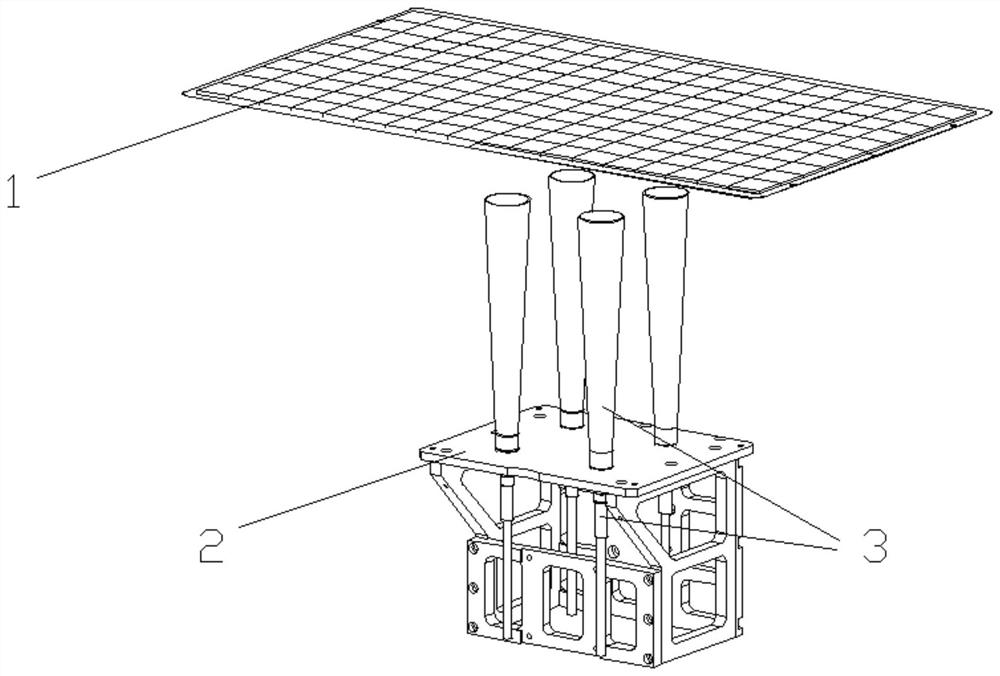
[0041] Such as figure 1 as shown, figure 1 The structure and position of the surface luminous body and the spectrometer matrix in the present invention are introduced. In this embodiment, four spectrometers are set to form the spectrometer matrix. The four spectrometers are fixed together by fixed brackets, and the surface luminous body is above the spectrometer matrix. Fixed by moving The bracket drives the spectrometer to move to detect the surface illuminant.

[0042] The spectrometer includes a spectrometer controller, a detection probe, an optical fiber line and a cosine diffuser. A detection probe, an optical fiber line and a micro-integrating sphere, the two ends of the optical fiber line are respectively connected to the spectrometer controller and the detection probe, and the micro-integrating sphere is installed at the end of the detection probe away from the optical fiber line.

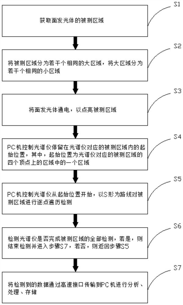
[0043] Such as image 3 as shown, image 3 A schematic flow diagram of the first me...

Embodiment 2

[0061] Compared with the first embodiment, this embodiment can improve detection efficiency on the basis of saving resources, and better meet the massive real-time data collection requirements of industrial production.

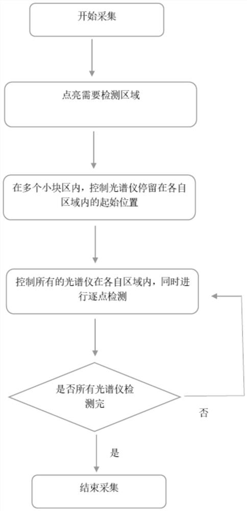
[0062] Such as Figure 5 as shown, Figure 5 A schematic flow diagram of the second method in the present invention is introduced, which specifically includes the following steps:

[0063] S1. Obtain the measured area of ​​the surface light emitter.

[0064] S2. Dividing the measured area into several identical large areas, and dividing the large area into several identical small areas. Such as Figure 5 As shown, if the measured area is set to have M rows and N columns, then the entire measured area is divided into M×N large areas; if each large area is set to have m rows and n columns, each large area is divided into Divided into m×n small areas.

[0065] S3. Turn on the surface light emitter to light up the area to be measured.

[0066] S4, the number...


PUM


Abstract

The invention provides a two-dimensional luminescence detection method for surface illuminant, which is characterized by comprising the following steps: a detected area of a surface illuminant is acquired; the detected area is divided into a plurality of same areas; the surface illuminant is electrified; the PC controls the spectrograph to stay at an initial position in a detected area corresponding to the spectrograph; the PC controls the spectrograph to carry out point-by-point traversal detection on the detected area by taking the S shape as a route from the initial position; whether the spectrograph completes all detection of the detected area or not is detected; and the detected data is transmitted to a PC through a high-speed interface to be analyzed, processed and stored. Accordingto the two-dimensional luminescence detection method for the surface illuminant provided by the invention, the spectrograph matrix is adopted to move along the specified path, so that each spectrograph in the spectrograph matrix is responsible for detection of the specified area, the detection efficiency is improved, and the mass real-time data acquisition requirement of industrial production canbe met.

Description

technical field [0001] The invention relates to the technical field of luminous body detection, in particular to a two-dimensional luminous detection method for a surface luminous body. Background technique [0002] The chromaticity, brightness or luminous body (such as LCD, LED) detection of existing light sources are mostly obtained by spectrometers. It has a wide range of applications in protection, biological and chemical detection, industrial and agricultural production, medical diagnosis and astronomical exploration; but there is a fatal flaw: the collection efficiency is extremely low and cannot meet the requirements of industrial production, and cannot be used for massive real-time data collection in industrial production Require. Contents of the invention [0003] The invention provides a two-dimensional luminescence detection method of a surface luminous body. The spectrometer matrix is ​​used to move along a specified path, so that each spectrometer in the spec...

Claims


Application Information

Patent Timeline
IPC IPC(8): G01M11/02G01J3/50G01J1/42
CPCG01M11/02G01J1/42G01J3/505G01J2001/4247G01J2001/4252
Inventor 刘永华
Owner 深圳市摩西尔工业检测设备有限公司
Learn More