
Stall protection crane

A crane and protection mechanism technology, applied in the field of stall protection cranes, can solve problems such as speed out of control, safety accidents, failures, etc.

Inactive Publication Date: 2020-10-20
湖南零陵恒远发电设备有限公司
View PDF0 Cites 0 Cited by
  • Summary
  • Abstract
  • Description
  • Claims
  • Application Information

AI Technical Summary

Problems solved by technology

[0003] However, the existing cranes must rely on electric motors to drive their operation.
For safety, it is limited to run within a certain speed, if it runs beyond the speed, it will cause accidental injury
Because the speed of the motor will be changed by factors such as frequency and voltage, when the inverter fails or is damaged, the speed will be out of control and a speeding accident will occur.
When falling rapidly, the transported objects will be damaged, the setting will hit the workers, causing safety accidents, and the sharp rise or fall will cause damage to the crane itself, the objects being carried, workshop equipment and personnel.
[0004] In the existing technology, some use sensors to detect the speed. When the speed is too high, the controller controls the motor to run at a reduced speed. The stability of this technology is not high enough. In the harsh environment of high temperature and high pressure, sensors, lines, Components such as controllers are easily damaged and malfunctioned, and some use locking devices, but such devices are only effective in the power-off state

Method used


Image

  • Stall protection crane
  • Stall protection crane
  • Stall protection crane

Examples


Embodiment Construction

[0071] In order to enable those skilled in the art to better understand the technical solution of the present invention, the present invention will be described in detail below in conjunction with the accompanying drawings. The description in this part is only exemplary and explanatory, and should not have any limiting effect on the protection scope of the present invention. .

[0072] It should be noted that like numerals and letters denote similar items in the following figures, therefore, once an item is defined in one figure, it does not require further definition and explanation in subsequent figures.

[0073] It should be noted that the orientation or positional relationship indicated by the terms "center", "upper", "lower", "left", "right", "vertical", "horizontal", "inner" and "outer" are Based on the orientation or positional relationship shown in the drawings, or the orientation or positional relationship that the inventive product is usually placed in use, it is onl...


PUM


Abstract

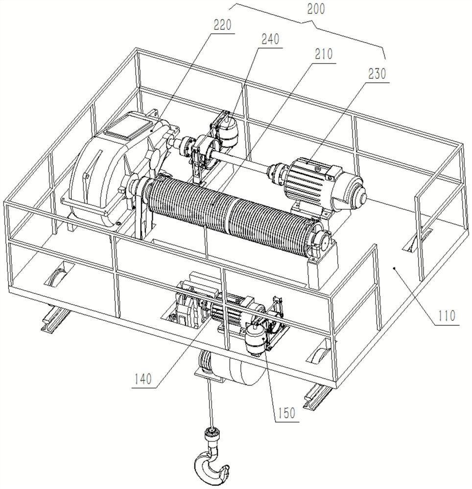
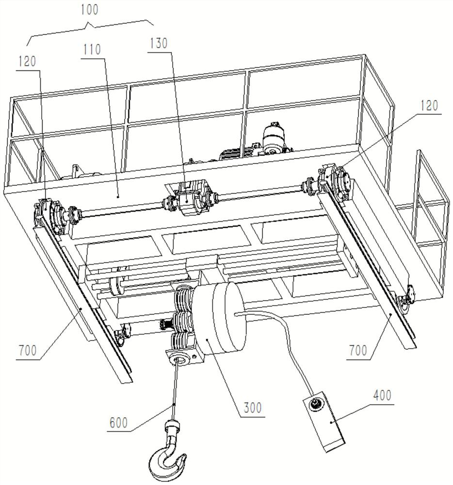
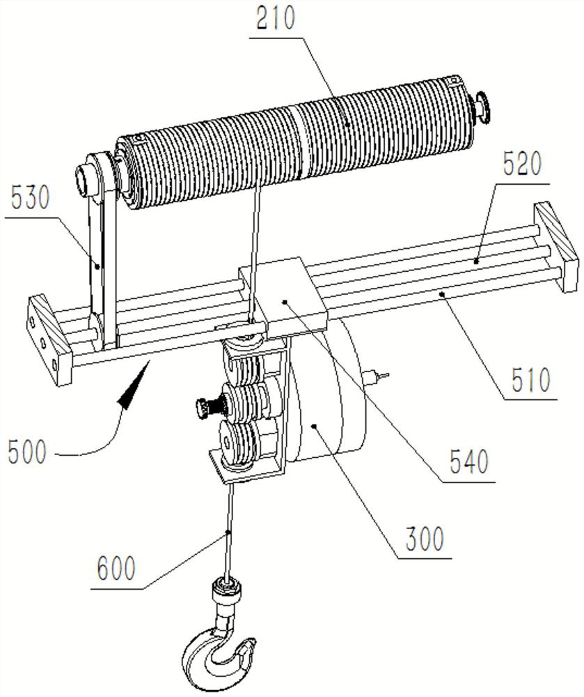
The invention discloses a stall protection crane. The stall protection crane comprises a walking mechanism, a lifting mechanism, a sliding mechanism and a stall protection mechanism, wherein the walking mechanism is arranged on a rail and can move along the rail; the lifting mechanism is connected with the walking mechanism and comprises a second driver and a roller which are arranged on a walkingframe body, and a rope body is wound on the roller; the sliding mechanism is connected with the lifting mechanism and moves along with the movement of the rope body; and the stall protection mechanism is connected with the sliding mechanism and winds the rope body to prevent the moving speed of the rope body from exceeding a preset value. After the rope body comes out of the roller, the rope bodywinds around the stall protection mechanism and then freely descends to hoist objects. When the rope body rises or falls at an overspeed in the running process, the speed of the rope body is limited,so that the rope body is limited to run within a preset value. Therefore, a good safety protection effect is achieved, out-of-control caused by motor faults and frequency converter faults is avoided,and equipment and personal safety is protected.

Description

technical field [0001] The invention relates to a lifting device, in particular to a stall protection crane. Background technique [0002] A crane refers to a multi-action hoisting machine that lifts vertically and carries heavy objects horizontally within a certain range. There are many kinds of cranes, including bridge cranes, cantilever cranes, elevators, and cranes for workshops. They are generally installed on the top of workshops and workshops, supported on the rails of the walls, and driven by motors to walk and lift back and forth to realize object lifting. Lifting and handling. [0003] However, the existing cranes all must rely on electric motors to drive their operation. For safety, it is limited to run within a certain speed, and if it runs beyond the speed, it will cause accidental injury. Because the speed of the motor will be changed by factors such as frequency and voltage, when the frequency converter fails or is damaged, the speed will be out of control ...

Claims


Application Information

Patent Timeline
IPC IPC(8): B66C9/08B66D1/28B66D1/54B66D1/12
CPCB66C9/08B66D1/12B66D1/28B66D1/54
Inventor 郭远军郭幸钢郭幸铜
Owner 湖南零陵恒远发电设备有限公司
Learn More