
Bismuth tungstate photocatalyst preparation device based on hydrodynamic cavitation and ultrasonic cavitation

A photocatalyst and preparation device technology, applied in catalyst activation/preparation, metal/metal oxide/metal hydroxide catalyst, physical/chemical process catalyst, etc., can solve the problem of inefficient large-scale bismuth tungstate nanophotocatalyst industry Chemical production, many preparation steps, large shrinkage and other problems

Active Publication Date: 2020-10-20
SHANDONG UNIV
View PDF11 Cites 2 Cited by
  • Summary
  • Abstract
  • Description
  • Claims
  • Application Information

AI Technical Summary

Problems solved by technology

It can be seen from practice that this method has certain advantages and disadvantages: the physical and chemical properties of the obtained sol are relatively uniform and stable, and the reaction can generally be carried out at room temperature; however, it consumes a lot of raw materials, the cost is high, and if people contact it for a long time, it will affect their health; Secondly, there are many preparation steps, and the reaction time is too long; finally, a large shrinkage will occur in the later processing process
[0016] The above method cannot carry out the industrial production of bismuth tungstate nano photocatalyst efficiently and on a large scale

Method used


Image

  • Bismuth tungstate photocatalyst preparation device based on hydrodynamic cavitation and ultrasonic cavitation
  • Bismuth tungstate photocatalyst preparation device based on hydrodynamic cavitation and ultrasonic cavitation
  • Bismuth tungstate photocatalyst preparation device based on hydrodynamic cavitation and ultrasonic cavitation

Examples


Embodiment Construction

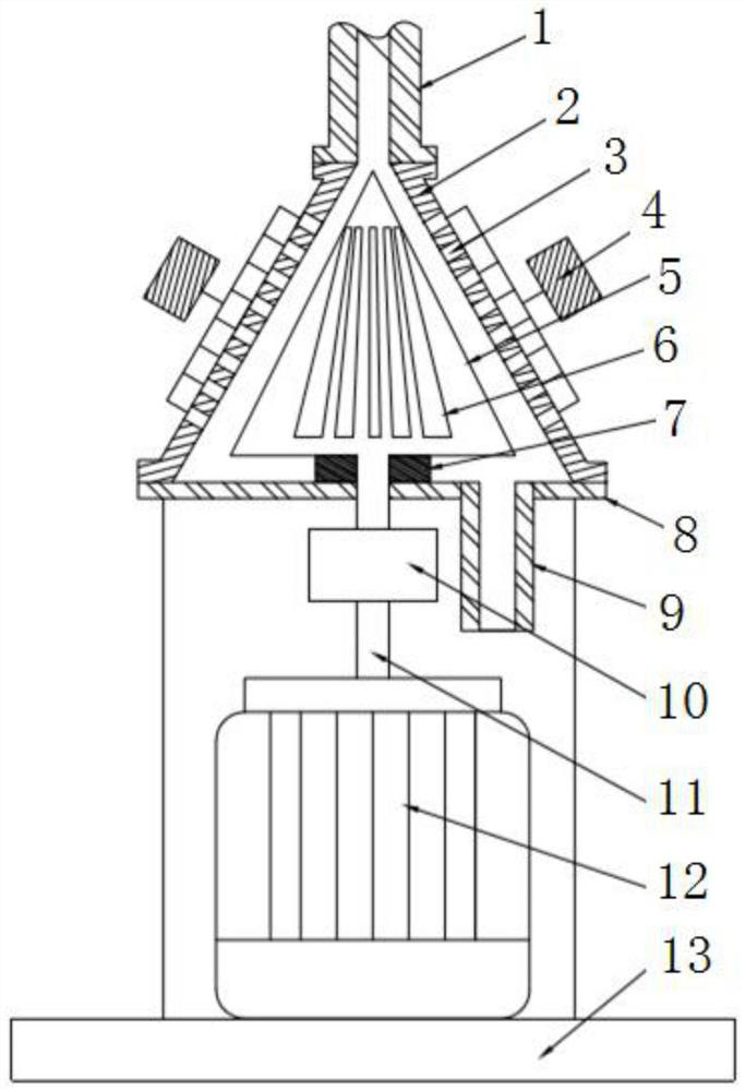
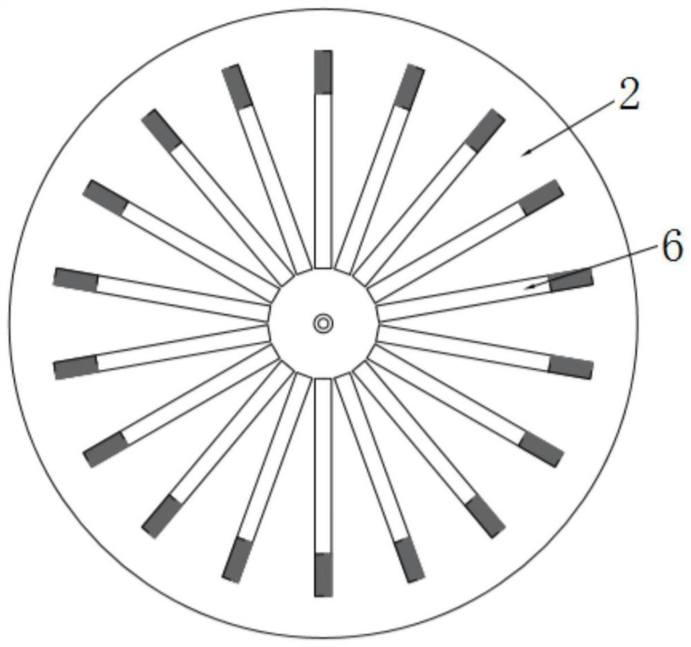
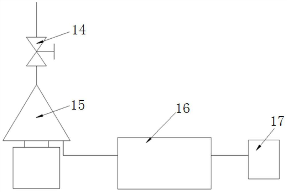
[0045] The structure of the bismuth tungstate photocatalyst preparation device 15 based on hydraulic cavitation and ultrasonic cavitation in the present invention is as follows figure 1 As shown, it includes a stator 2 , an ultrasonic transducer 3 , an ultrasonic generator 4 , a rotor 5 and a rotating shaft 11 . The stator 2 is a tapered airtight cavity, the bottom of the stator 2 is connected to the end cover 8 by bolts, and the bottom of the end cover 8 is supported on the base 13 . An ultrasonic transducer 3 is installed on the inner wall of the stator 2 . Each ultrasonic transducer 3 is connected to an ultrasonic generator 4 . The ultrasonic transducers 3 are embedded in the inner wall of the stator along the axial and circumferential directions in the form of 2 to 8 in each row, 2 to 6 rows in total, and equally spaced. The number of ultrasonic generators 4 is 1-4, the frequency is above 20kHz, and the power of a single machine is 1500-3000W. After coupling ultrasonic ...


PUM

PropertyMeasurementUnit
Depthaaaaaaaaaa

Abstract

The invention discloses a bismuth tungstate photocatalyst preparation device based on hydrodynamic cavitation and ultrasonic cavitation. The bismuth tungstate photocatalyst preparation device comprises a stator, an ultrasonic cavitation transducer, a rotor and a rotating shaft, wherein the stator is a closed cavity, ultrasonic transducers are distributed on the inner wall of the stator, a feedingpipe is arranged at the upper end of the stator, a discharging pipe is arranged at the lower end of the stator, the rotor is arranged in the stator and fixedly connected with the upper end of the rotating shaft, the rotating shaft is vertically installed in the stator, the lower end of the rotating shaft extends out of the stator, and grooves are distributed in the outer wall of the rotor. According to the device, the bismuth tungstate preparation reaction is strengthened at room temperature through efficient coupling of hydrodynamic cavitation and ultrasonic cavitation phenomena, and the reaction of raw materials is accelerated under extremely high-temperature and high-pressure conditions generated by the cavitation effect; shock waves, micro-jet flow and other phenomena generated by thecavitation effect can greatly change the surface appearance of the generated catalyst and increase the specific surface area, so that the catalytic performance is improved; and the device has the advantages of large treatment capacity, continuous operation and low cost, and has a wide application prospect in the field of nano-catalyst preparation.

Description

technical field [0001] The invention relates to a preparation device of a bismuth tungstate photocatalyst based on hydraulic cavitation and ultrasonic cavitation, and belongs to the technical field of bismuth tungstate photocatalytic material preparation. Background technique [0002] Bismuth tungstate (Bi 2 WO 6 ) is a new type of photocatalyst, which has a wide range of application prospects in sterilization, dielectric, photocatalysis, etc. due to its non-toxic, high-efficiency, and low-cost characteristics. The current preparation methods include solid phase sintering method, precipitation method, sol-gel method, hydrothermal method, solvothermal method and so on. [0003] 1. Solid phase sintering method [0004] The solid-phase sintering method is a relatively early method of preparing powders. Previously, bismuth tungstate (Bi 2 WO 6 ) Most powders use this method. The method is obtained by mechanically mixing oxides containing Bi and W or their salts and then di...

Claims


Application Information

Patent Timeline
IPC IPC(8): B01J23/31B01J37/34B01J37/00
CPCB01J23/31B01J37/00B01J37/343
Inventor 孙逊陈颂英玄晓旭张光超郭姣
Owner SHANDONG UNIV
Learn More