
Support

A technology of support unit and rotator, applied in the field of medical devices, can solve problems such as delay of vascular endothelialization, influence on hemodynamics, formation, etc.

Pending Publication Date: 2020-10-20
SHANGHAI MICROPORT MEDICAL (GROUP) CO LTD
View PDF0 Cites 0 Cited by
  • Summary
  • Abstract
  • Description
  • Claims
  • Application Information

AI Technical Summary

Problems solved by technology

However, thicker stents are prone to affect hemodynamics, which may lead to the formation of stent thrombosis, and thicker stents lead to delayed endothelialization and healing.

Method used


Image

  • Support
  • Support
  • Support

Examples


Embodiment 1

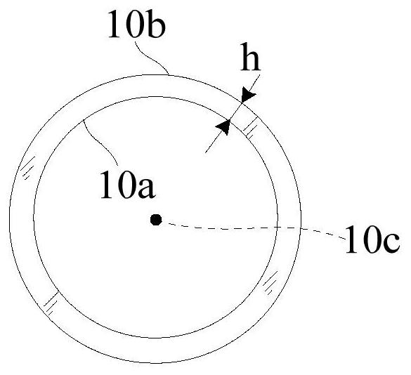
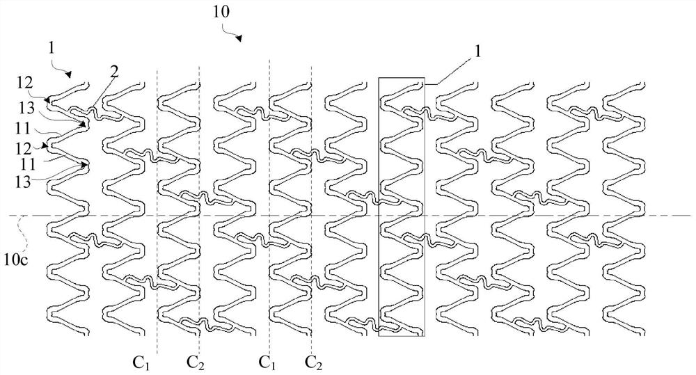
[0042] refer to figure 1As shown, the stent 10 provided by an embodiment of the present application includes a plurality of support unit rings 1 and a plurality of connecting rods 2, and the plurality of connecting rods 2 connect the plurality of support unit rings 1 along the axial direction 10c of the stent 10 into a For the network tubular structure, understandably, the extending direction of the central axis of the formed network tubular structure is the axial direction 10c of the stent 10 . structure figure 2 As shown, after a plurality of support units are connected by a plurality of connecting rods 2 to form a network tubular structure, when viewed along the axial direction 10c of the stent 10, it will be in the shape of a ring, that is, it has an opposite inner surface 10a and an outer surface 10b, the stent The wall thickness h of 10 is the distance between the inner surface 10a and the outer surface 10b.

[0043] combine image 3 as shown, image 3 for figure 1...

Embodiment 2

[0077] The bracket 10 of this embodiment is the same in composition and connection as in Embodiment 1, except that the number of first turning parts 12 or second turning parts 13 is 9-12, for example 9, 10, 11 or 12. The number of connecting rods 2 is 3-5, such as 3, 4 or 5. The stent 10 formed in this way can adapt to blood vessels with larger diameters and has excellent expandability.

Embodiment 3

[0079] Such as Figure 7 As shown, the structure of the supporting unit ring 1" of the bracket 30 in this embodiment is the same as that of Embodiment 1, and only the structure of the connecting rod 2" is different. Specifically, in the bracket 30 in this embodiment, the connecting rod 2" adopts Relatively smooth structure. The connecting rod 2” includes multiple arc segments, except that the arc segment at the position connected to the support unit ring 1” has obvious curvature, and the radius of curvature is 0.05mm to 0.15mm, such as 0.05mm, 0.1mm Or 0.15mm. The radius of curvature of the arc section in other places is relatively large, and they are connected smoothly. This makes the crimping diameter of the stent 30 smaller, and improves the lesion-passing ability and pushing ability of the stent 30 .


PUM

PropertyMeasurementUnit
Radius of curvatureaaaaaaaaaa
Lengthaaaaaaaaaa
Lengthaaaaaaaaaa

Abstract

The invention relates to a support. The support comprises a plurality of supporting unit loops, wherein each supporting unit loop comprises a plurality of columns, a plurality of proximal end turningparts and a plurality of distal end turning parts, the proximal end turning parts and the distal end turning parts are alternately connected to proximal ends and distal ends of the columns so as to enable the supporting unit loops to form a closed structure, and the proximal end turning parts and the distal end turning parts are separately provided with concave cambered surfaces and convex cambered surfaces which are contrary to each other. According to the support disclosed by the invention, through improving structures of the proximal and distal end turning parts of the supporting unit loopsof the support, higher extruding resistance is obtained, so that the support is not easily collapsed by pressure and maintains good supporting performance on a vascular wall; and in case of maintaining a sufficient supporting force, the wall thickness of the support with such a structure can be reduced as much as possible, and the probability of occurrence of thrombosis and vascular endothelium delayed healing caused by support wall thickness influence is lowered.

Description

technical field [0001] The invention relates to the technical field of medical instruments, in particular to an intraluminal stent. Background technique [0002] Interventional therapy is the introduction of special precision instruments into the human body under the guidance of medical imaging equipment to diagnose and locally treat lesions in the body. Because interventional therapy has the characteristics of no surgery, less trauma, quick recovery and good effect, interventional technology has been popularized and developed in recent years. Among them, percutaneous coronary intervention (PCI) has been more and more widely used in the treatment of heart disease caused by coronary atherosclerosis. This method is mainly completed by implanting an expandable cylindrical mesh stent at the diseased blood vessel. After the stent is implanted, the stent is expanded to open the stenotic blood vessel to achieve the purpose of treatment. [0003] The stent is an implantable device...

Claims


Application Information

Patent Timeline
IPC IPC(8): A61F2/915
CPCA61F2/915A61F2002/9155
Inventor 顾凡周奇李俊菲
Owner SHANGHAI MICROPORT MEDICAL (GROUP) CO LTD
Learn More