
Shielding case assembly

A shielding cover and component technology, applied in the fields of magnetic field/electric field shielding, electrical components, electrical equipment structural parts, etc., can solve problems such as affecting heat dissipation efficiency, blocking air flow, etc., to improve heat dissipation efficiency, increase heat dissipation efficiency, and facilitate assembly. with fast effects

Pending Publication Date: 2020-10-16
MOLEX INC
View PDF13 Cites 0 Cited by
  • Summary
  • Abstract
  • Description
  • Claims
  • Application Information

AI Technical Summary

Problems solved by technology

[0005] Chinese Utility Model Patent Application No. CN200920006325.5 (corresponding to U.S. Patent No. US7601021) discloses a connector assembly, which discloses that there are grooves on both sides of the heat sink buckle, and the positions of the light guide columns corresponding to the grooves are respectively A cylinder is inserted into the groove, and the direction of the plate surface of the groove is to face the front-to-back direction, so it will block the air flow flowing in the front-to-back direction and affect the heat dissipation efficiency
[0006] Chinese Utility Model Patent Application No. CN201120303406.9 discloses a connector. The lug used to fix the light guide column is arranged on the upper bottom plate (the top wall of the housing), and the direction of the plate surface of the lug is facing the front and rear directions. Therefore, the air flow flowing in the front and rear directions will be blocked, which will affect the heat dissipation efficiency.

Method used


Image

  • Shielding case assembly
  • Shielding case assembly
  • Shielding case assembly

Examples


Embodiment Construction

[0163] Before the present invention is described in detail, it should be noted that in the following description, similar elements are denoted by the same numerals.

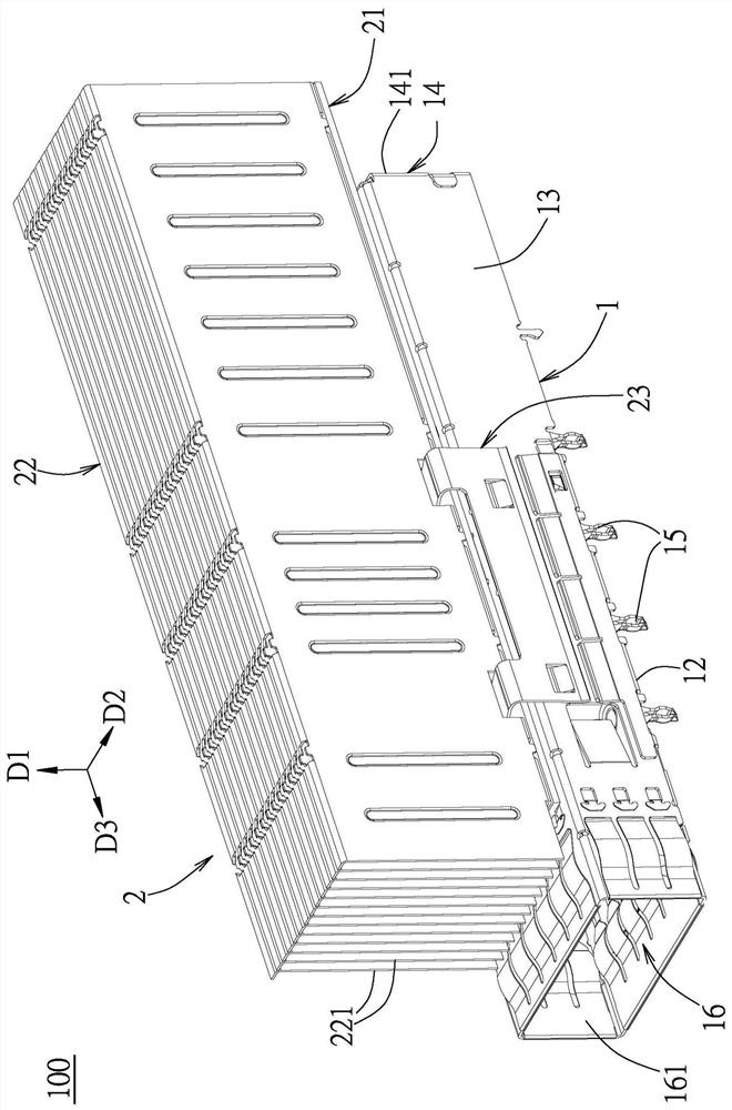
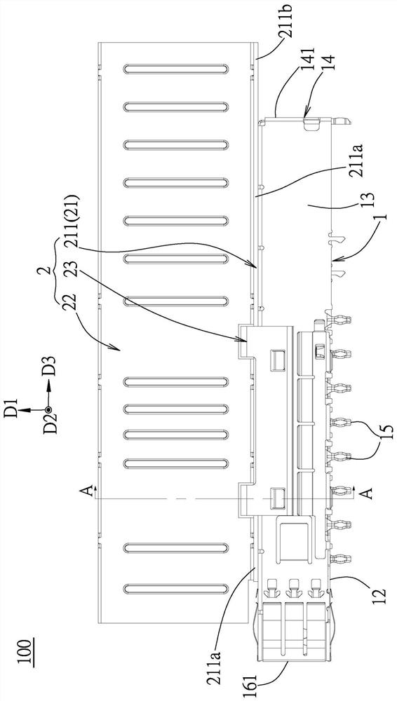
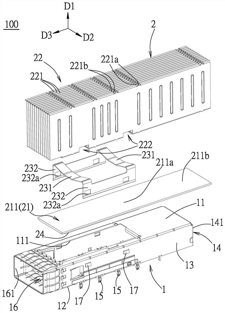
[0164] Figure 1 to Figure 6 For a first embodiment of the shield assembly 100 of the present invention, see figure 1 and figure 2 , the first embodiment includes a metal shielding case 1 and a heat dissipation module 2 .

[0165] refer to figure 2 and image 3 , the metal shielding case 1 is made of a metal plate and is used to accommodate electronic modules (including sockets and plugs, not shown in the figure), the metal shielding case 1 has a plurality of walls, and a housing composed of a plurality of said walls In the space 16, a plurality of walls include a top wall 11, a bottom wall 12 spaced opposite to the top wall 11 along a vertical direction D1, two spaced apart from each other along a left-right direction D2, and connected to the bottom wall 12 and the bottom wall 12 respectively. The side wa...


PUM


Abstract

A shielding case assembly comprises a metal shielding shell and a heat dissipation module. The metal shielding shell comprises a plurality of walls and an accommodating space defined by the pluralityof walls, and the accommodating space is provided with a front-end socket. The heat dissipation module is assembled on one wall of the metal shielding shell; the heat dissipation module comprises a hot plate which is connected to the metal shielding shell in a covering manner and is used for assembling the wall of the heat dissipation module; the hot plate comprises a first section used for covering the wall of the metal shielding shell and extending backwards to the rear side edge of the wall, and a second section which extends backwards out of the rear portion of the metal shielding shell from the rear side of the first section; and the heat dissipation module further comprises a first heat dissipation piece which is arranged on the top face of the hot plate and extends from the first section to the second section.

Description

[0001] This application is a divisional application of an invention patent application with the applicant "Moles Co., Ltd.", the application date is September 26, 2018, the application number is 2018111251035, and the invention name is "shielding cover assembly". technical field [0002] The invention relates to a shielding cover assembly, in particular to a shielding cover assembly with a heat dissipation structure and a light guiding structure. Background technique [0003] Chinese Utility Model Patent Grant No. CN2450707Y (corresponding to U.S. Patent No. US6373699) discloses a heat dissipation device, which discloses that a buckle is accommodated in the slot of the blade body and is closely attached to the top surface of the base. Heat dissipation structure in the chip field. In the field of high-speed connectors with metal shielding shells, it is necessary to conceive different structures and create a heat dissipation effect with higher heat dissipation efficiency under...

Claims


Application Information

Patent Timeline
Patent Type & Authority Applications(China)
IPC IPC(8): H05K9/00H05K7/20
CPCH05K7/20409H05K9/0007H05K7/2039
Inventor 吕友谦
Owner MOLEX INC
Learn More