
Plasma synthetic jet exciter suitable for high-pressure condition

A plasma and synthetic jet technology, applied in the direction of plasma, electrical components, etc., can solve the problems of high breakdown voltage, poor jet effect, low flexibility, etc., to reduce breakdown voltage, improve performance, and improve jet effect. Effect

Inactive Publication Date: 2020-10-16
AIR FORCE UNIV PLA
View PDF5 Cites 6 Cited by
  • Summary
  • Abstract
  • Description
  • Claims
  • Application Information

AI Technical Summary

Problems solved by technology

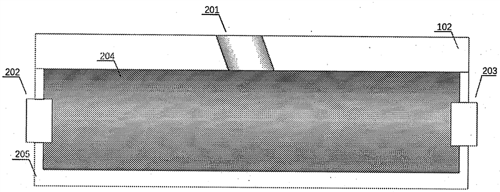
[0005] In view of this, in view of the outstanding problems such as high breakdown voltage, poor jet effect, and low flexibility when the current plasma synthetic jet actuator is applied to the control of the internal flow field of the engine, the present invention proposes a The plasma synthetic jet exciter 103 comprises an exciter body 101 and a sheet-shaped rectangular cover plate 102, and the exciter body 101 includes an anode discharge electrode 202, a cathode discharge electrode 203, a semiconductor coating 204, and an exciter housing 205; wherein

Method used


Image

  • Plasma synthetic jet exciter suitable for high-pressure condition
  • Plasma synthetic jet exciter suitable for high-pressure condition

Examples


specific Embodiment

[0026] Considering that the use environment is mainly the inner wall of the engine with high temperature and pressure, the main body 101 and the cover plate 102 of the plasma synthetic jet actuator are made of alumina ceramics. The inner cavity of the exciter housing 205 has a diameter of 5 mm, a length of 9 mm, a wall thickness of 2 mm, and a chord length of 6 mm on the vertical section. The cover plate is 13 mm long, 12 mm wide, and 1.5 mm thick. The jet hole 201 forms an angle of 15 degrees with the normal direction of the upper surface of the cover plate 102 . The anode discharge electrode 202 and the cathode discharge electrode 203 are made of tungsten needles with a radius of 1 mm.


PUM


Abstract

A plasma synthetic jet exciter used under a high air pressure condition comprises an exciter body and a sheet-shaped rectangular cover plate; the exciter body comprises an anode discharge electrode, acathode discharge electrode, a semiconductor coating and an exciter shell. The top of the exciter shell is connected with the lower surface of the cover plate in a sealing manner, the cover plate isprovided with inclined straight-through jet holes from top to bottom, the left end panel and the right end panel of the exciter shell are provided with through holes, and the anode discharge electrodeand the cathode discharge electrode extend into the exciter shell through the through holes. Aiming at a working environment with high flow pressure in a combustion chamber, the discharge voltage between the cathode and the anode is greatly reduced by utilizing the semiconductor coating; therefore, the exciter can still maintain a large electrode distance under high air pressure; meanwhile, the conversion efficiency of discharge energy is improved and the jet flow effect of the exciter is improved by utilizing a large discharge cavity volume and the geometric structure of the vertically-cut cylinder, thereby solving the problem that the exciter is not suitable for a ramjet combustion chamber in the prior art.

Description

technical field [0001] The present invention relates to plasma technology, in particular to a high-efficiency plasma synthetic jet actuator that works under high-pressure conditions through semiconductors and new structures, and more specifically to a plasma synthetic jet actuator suitable for high-pressure conditions . Background technique [0002] Plasma synthetic jet actuator is an active flow control device for high-speed flow field that relies on spark discharge to generate high-energy jet, and then exerts effective disturbance on the flow. Compared with other flow control methods, the plasma synthetic jet actuator has the advantages of no external gas source, wide operating frequency range, high jet velocity, and strong environmental adaptability. , A form of flow control actuator that is more likely to achieve breakthroughs in practical engineering applications. [0003] In the current field of flow control research, the plasma synthetic jet actuator is generally ap...

Claims


Application Information

Patent Timeline
Patent Type & Authority Applications(China)
IPC IPC(8): H05H1/48H05H1/24
CPCH05H1/48H05H1/24
Inventor 吴云张志波贾敏崔巍宋慧敏金迪梁华
Owner AIR FORCE UNIV PLA
Learn More