
Stranding machine for cable production

A stranding machine and stranding technology, applied in cable/conductor manufacturing, circuits, electrical components, etc., can solve problems such as cable slack, limited cable length, and reduced work efficiency, and achieve easy replacement, convenient fixation, and avoidance. The effect of different tension

Active Publication Date: 2020-10-16
JING FENG GRP
View PDF7 Cites 6 Cited by
  • Summary
  • Abstract
  • Description
  • Claims
  • Application Information

AI Technical Summary

Problems solved by technology

[0003] When the stranding machine is working, it will place multiple pay-off reels with cables on the pay-off rod. In order to prevent the pay-off reel from falling off on the pay-off rod, the pay-off reel is generally threaded on the pay-off rod. It is more troublesome, and because the length of the cable on the pay-off wheel is limited, it needs to be replaced, which reduces the work efficiency. There are many cables, and the cables are loose during the twisting process, which affects the quality of the cables after twisting.

Method used


Image

  • Stranding machine for cable production
  • Stranding machine for cable production
  • Stranding machine for cable production

Examples


Embodiment Construction

[0027] The following will clearly and completely describe the technical solutions in the embodiments of the present invention with reference to the accompanying drawings in the embodiments of the present invention. Obviously, the described embodiments are only some, not all, embodiments of the present invention.

[0028] In describing the present invention, it should be understood that the terms "upper", "lower", "front", "rear", "left", "right", "top", "bottom", "inner", " The orientation or positional relationship indicated by "outside", etc. is based on the orientation or positional relationship shown in the drawings, and is only for the convenience of describing the present invention and simplifying the description, rather than indicating or implying that the referred device or element must have a specific orientation, so as to Specific orientation configurations and operations, therefore, are not to be construed as limitations on the invention.

[0029] refer to Figure ...


PUM


Abstract

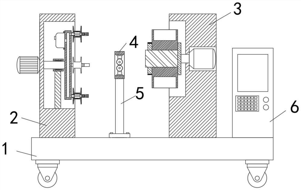
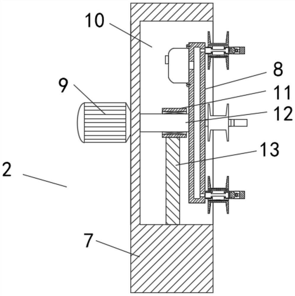
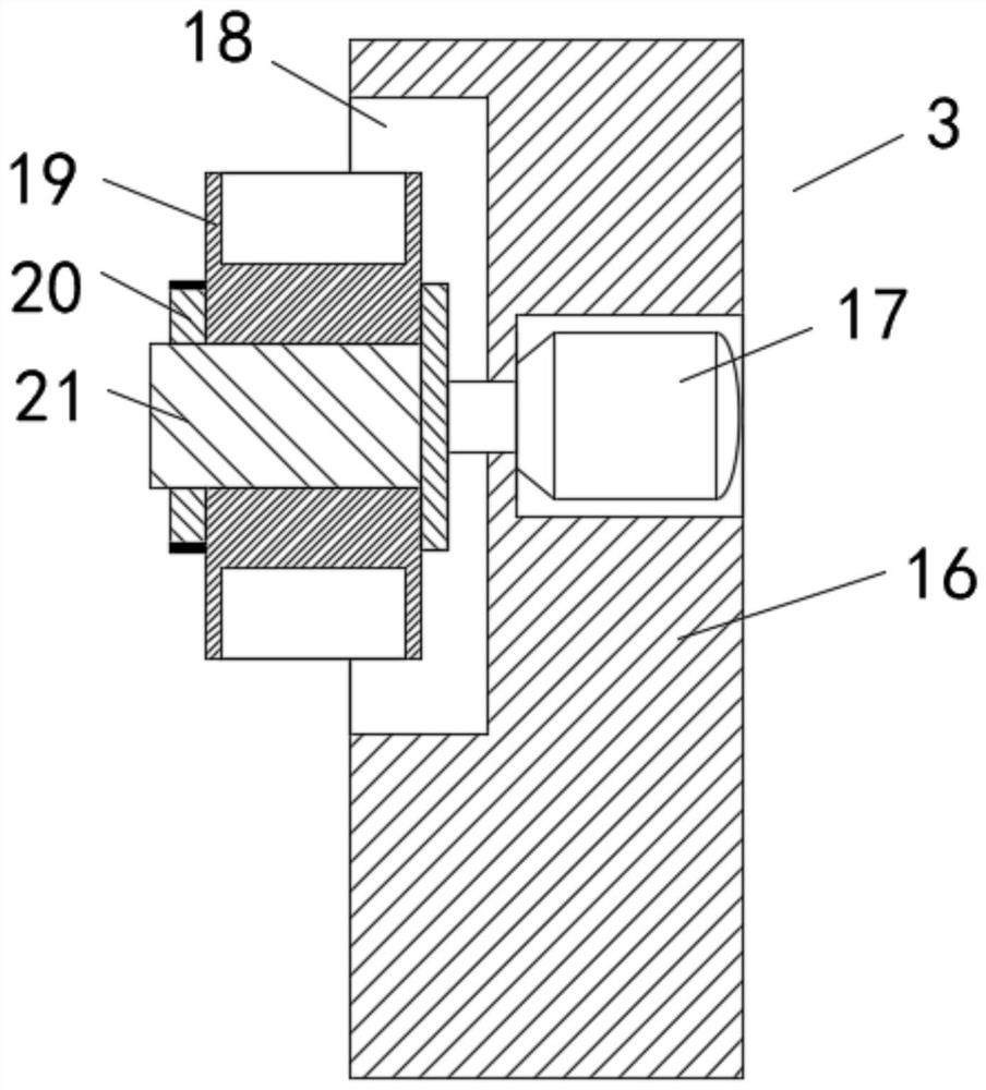
The invention discloses a stranding machine for cable production. The stranding machine comprises a base, a stranding device, a coiling device and a communication block, wherein the stranding device and the coiling device are fixed on the base; the communication block is located between the stranding device and the coiling device, the bottom face of the communication block is fixedly connected with a supporting rod, the lower end of the supporting rod is fixed to the base, a control box is further fixed to the base, the stranding device comprises a stranding box, and a stranding cavity is formed in the stranding box. According to the stranding machine, the pay-off wheel placed on a pay-off rod can be fixed conveniently, when a cable on the pay-off wheel is used up and needs to be replaced,a valve on a rotary disc is opened at the moment, compressed air is exhausted, a sliding block is collected into an air channel under the action of the spring, and the pay-off wheel is convenient toreplace.

Description

technical field [0001] The invention relates to the technical field of cable processing, in particular to a stranding machine for cable production. Background technique [0002] The cable is usually a rope-like cable twisted by several or several groups of wires (at least two in each group). Each group of wires is insulated from each other and is often twisted around a center. Insulated covering layer, the cable has the characteristics of internal energization and external insulation. The cables include power cables, control cables, compensation cables, shielded cables, high temperature cables, computer cables, signal cables, coaxial cables, fire-resistant cables, marine cables, and mining cables. cables, aluminum alloy cables, etc. [0003] When the stranding machine is working, it will place multiple pay-off reels with cables on the pay-off rod. In order to prevent the pay-off reel from falling off on the pay-off rod, the pay-off reel is generally threaded on the pay-off ...

Claims


Application Information

Patent Timeline
IPC IPC(8): H01B13/02B65H54/44B65H49/30B65H59/10
CPCH01B13/02H01B13/0207B65H54/44B65H49/30B65H59/10
Inventor 许义彬
Owner JING FENG GRP
Learn More