Walking trolley equipment for searching optical cable surface biting wound

A traveling trolley and optical cable technology, applied in the field of communication, can solve the problems of optical cable damage, difficult sliding operation, delay in repair time and other problems

Pending Publication Date: 2020-10-16
STATE GRID ZHEJIANG ELECTRIC POWER CO LTD QUZHOU POWER SUPPLY CO
View PDF0 Cites 2 Cited by
  • Summary
  • Abstract
  • Description
  • Claims
  • Application Information

AI Technical Summary

Problems solved by technology

[0002] ADSS optical cable is an all-dielectric self-supporting optical cable. It is a non-metallic optical cable line erected on the same pole as the existing transmission line. ADSS optical cable is composed of outer sheath, aramid fiber layer, inner sheath and optical unit. The aramid fiber layer is The main stress unit of the optical cable, when the outer sheath and aramid layer of the optical cable are damaged by external forces such as small animals, the main stress unit of the optical cable has been damaged, and the power ADSS optical cable is erected on the same pole along the 110kV power transmission line , which means that the spans are all over 100 meters, and the erection locations are all in mountainous areas, with large height differences. If construction workers are used to hang on the line to find the fault location of the optical cable, the weight of the workers plus the weight of the tools is about 75KG. It is difficult to slide on the optical cable, and it will also cause damage to the optical cable, which can easily cause personal fall accidents
[0003] Further, in order to solve this problem, drones are generally used to capture the surface conditions of the optical cable to find the breakpoint position of the ADSS optical cable line; It is often difficult to see the tiny wounds on the ground, which leads to delays in emergency repairs. On the other hand, the environment where ADSS optical cables are erected is often in the bushes, and drones cannot fly in, resulting in the inability to continuously and clearly collect the complete surface conditions of the optical cables.

Method used


Image

  • Walking trolley equipment for searching optical cable surface biting wound
  • Walking trolley equipment for searching optical cable surface biting wound
  • Walking trolley equipment for searching optical cable surface biting wound

Examples


specific Embodiment 1

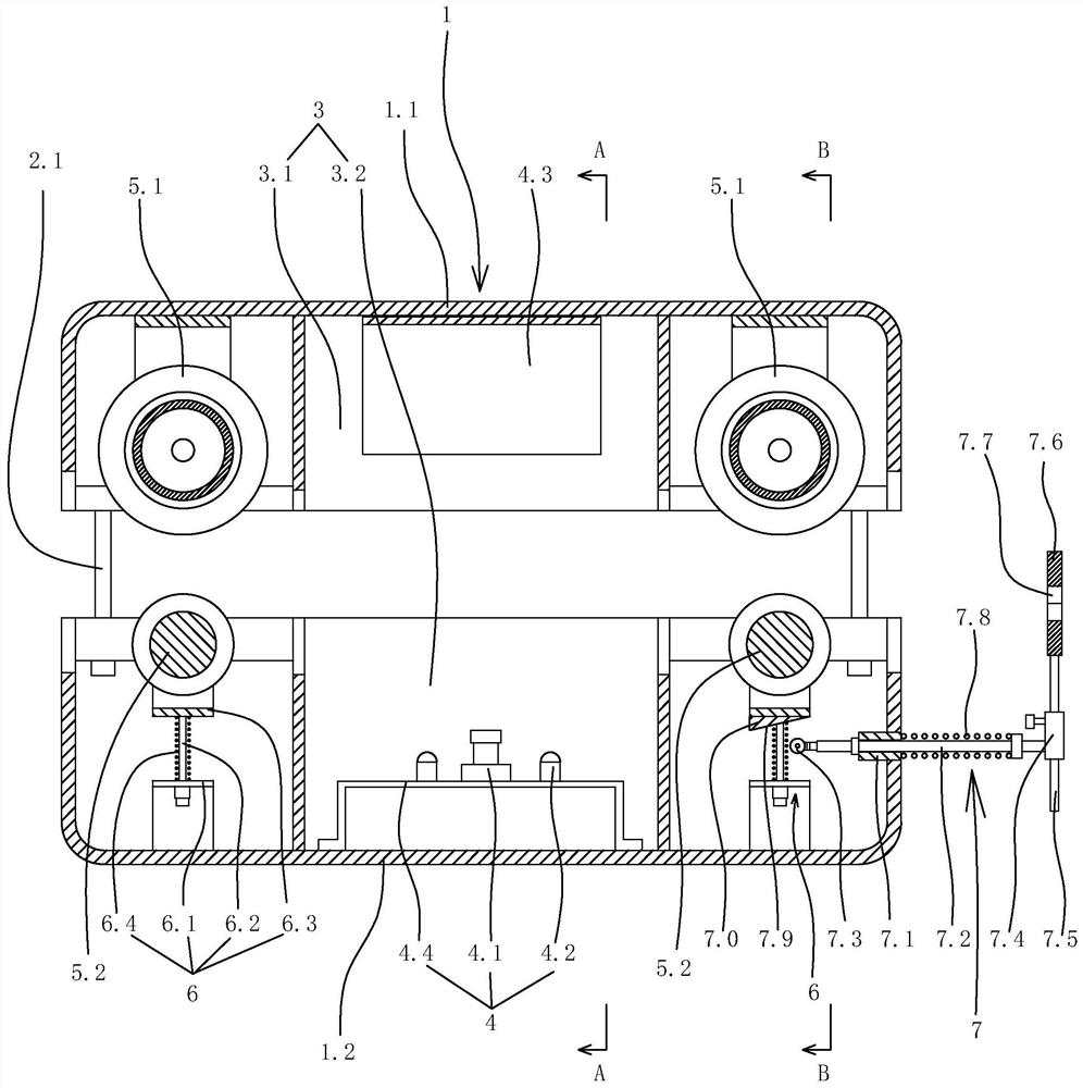
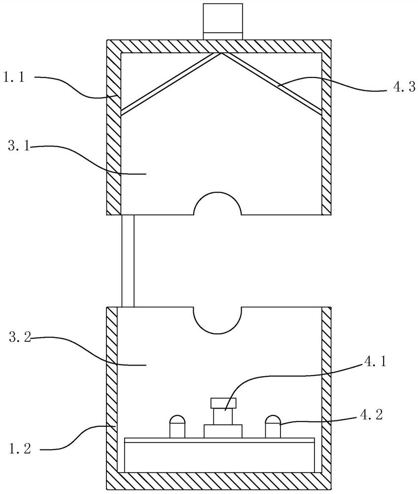
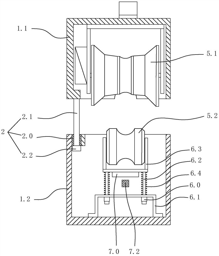
[0041] Specific embodiment one: as figure 1 , figure 2 , Figure 5 As shown, a walking trolley device for finding gnawing wounds on the surface of an optical cable includes a walking trolley, a detection darkroom 3 and a gnawing wound detection device 4 . The walking trolley is suspended on the ADSS optical cable 8 and can walk along the ADSS optical cable. A closed cavity is arranged inside the walking trolley, and the cavity constitutes a detection chamber 3 through which the ADSS optical cable passes. The gnawing wound detection device includes a 365nm ultraviolet lamp 4.2 and a camera 4.1 arranged in the detection darkroom, and the camera is used to photograph the ADSS optical cable located in the detection darkroom. The gnawing wound refers to the gnawing wound left by small animals such as squirrels when gnawing on the optical cable.

[0042] The gnawing wounds left by small animals such as squirrels when they gnaw on optical cables are generally relatively small, ...


PUM


Abstract

The invention discloses walking trolley equipment for searching an optical cable surface biting wound, which aims to provide the walking trolley equipment capable of clearly and accurately searching for the biting wound generated by biting of small animals on an ADSS optical cable line. The equipment comprises a walking trolley, a detection darkroom and a biting wound detection device, wherein thewalking trolley is suspended on an ADSS optical cable and can walk along the ADSS optical cable; a closed cavity is formed in the walking trolley, the cavity forms the detection darkroom, and the ADSS optical cable penetrates through the detection darkroom; the biting wound detection device comprises a 365 nm ultraviolet lamp and a camera which are arranged in the detection darkroom, and the camera is used for shooting the ADSS optical cable located in the detection darkroom.

Description

technical field [0001] The invention relates to the search for the position of the optical cable wound of an overhead optical cable line in the field of communication technology, and in particular to a walking trolley device for searching the gnawing wound on the surface of the optical cable. Background technique [0002] ADSS optical cable is an all-dielectric self-supporting optical cable. It is a non-metallic optical cable line erected on the same pole as the existing transmission line. ADSS optical cable is composed of outer sheath, aramid fiber layer, inner sheath and optical unit. The aramid fiber layer is The main stress unit of the optical cable, when the outer sheath and aramid layer of the optical cable are damaged by external forces such as small animals, the main stress unit of the optical cable has been damaged, and the power ADSS optical cable is erected on the same pole along the 110kV power transmission line , which means that the spans are all over 100 meter...

Claims


Application Information

Patent Timeline
IPC IPC(8): G01N21/33G01N21/01G01V9/00G02B6/44
CPCG01N21/33G01N21/01G01V9/00G01N2021/0112G02B6/564
Inventor 杨永峰周茜许屹姜正德
Owner STATE GRID ZHEJIANG ELECTRIC POWER CO LTD QUZHOU POWER SUPPLY CO
Why Eureka
Try Eureka