Dust removal and humidification device used for automated textile machine

A humidification device and textile machinery technology, which is applied in the processing of textile material equipment configuration, mechanical cleaning, textile and paper making, etc. Even and thorough spraying and moisturizing, better moisturizing effect, and the effect of expanding the spraying range

Pending Publication Date: 2020-10-16
张爱兰
View PDF1 Cites 0 Cited by
  • Summary
  • Abstract
  • Description
  • Claims
  • Application Information

AI Technical Summary

Problems solved by technology

[0005] The purpose of the present invention is to provide a dust removal and humidification device for automatic textile machinery, to solve the problem that the brushing parts proposed in the above-mentioned background technology are mostly installed statically, and most of them use the traction movement of the weaving cloth itself to achieve relative friction and dust removal, resulting in brushing. The friction and dust removal force between the parts and the fabric is low, and the dust removal and cleaning effect is not good.

Method used


Image

  • Dust removal and humidification device used for automated textile machine
  • Dust removal and humidification device used for automated textile machine
  • Dust removal and humidification device used for automated textile machine

Examples


Embodiment Construction

[0027] The following will clearly and completely describe the technical solutions in the embodiments of the present invention with reference to the accompanying drawings in the embodiments of the present invention. Obviously, the described embodiments are only some, not all, embodiments of the present invention.

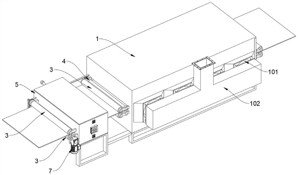
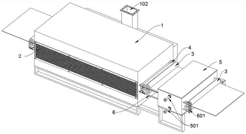
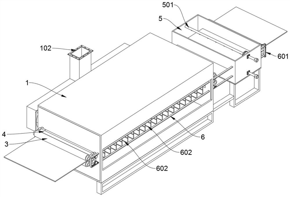
[0028] see Figure 1 to Figure 8 , an embodiment provided by the present invention: a dust removal and humidification device for automatic textile machinery, including a dust removal box 1, the dust removal box 1 includes a dust extraction fan 101 and a dust discharge pipe 102, and the dust removal box 1 is in a rectangular shape as a whole The middle position of the front and rear side walls is provided with a cloth threading trough, and two brush rollers 4 and two guide rollers 3 are installed symmetrically on the walls adjacent to the upper and lower sides of the two cloth threading troughs. , and the left side wall of the dust removal box 1 is provided with a hor...


PUM


Abstract

The invention discloses a dust removal and humidification device used for an automated textile machine, relates to the technical field of textile equipment, and solves the problems that most brushingand wiping components of an existing dust removal and humidification device are statically installed, relative friction dust removal is usually realized through the own traction movement of woven cloth, so that the friction dust removal strength of the brushing and wiping component and the woven cloth is low and a dust removal and cleaning effect is poor. The dust removal and humidification deviceused for the automated textile machine comprises a dust removal box, wherein the dust removal box comprises a dust suction fan and is integrally of a rectangular structure; a cloth penetration grooveindependently penetrates through the middle position of the front side wall and the middle position of the rear side wall of the dust removal box; wall surfaces on the adjacent positions of the uppersides and the lower sides of the two cloth penetration grooves are symmetrically rotatably spliced with two brush rolls and two guiding compression rolls; and a lateral rectangular air suction grooveis penetrated on the left side wall of the dust removal box. Four brush rolls in the dust removal and humidification device have a certain blocking and sealing function through brushes on the brush rolls, and a situation that a great quantity of dust in the dust removal box outwards leaks can be avoided.

Description

technical field [0001] The invention relates to the technical field of textile equipment, in particular to a dust removal and humidification device for automatic textile machinery. Background technique [0002] In the process of textile production, many processes are required from raw material processing to weaving into cloth. Each process will produce fluff, dust, etc., causing serious pollution to the environment and causing harm to the human body. When dust, cotton fluff, etc. enter If it enters the equipment, it is easy to cause equipment failure, cause production stagnation, and affect production efficiency. In addition, there are a lot of equipment in the textile workshop and a lot of heat dissipation, which will generate a lot of waste heat and humidity, which will have a great impact on the production of textiles. Therefore, it is necessary to carry out comprehensive treatment of dust removal and humidification in the production process of textile products to avoid p...

Claims


Application Information

Patent Timeline
Patent Type & Authority Applications(China)
IPC IPC(8): D06B1/02D06B23/20D06G1/00
CPCD06B1/02D06B23/20D06G1/00
Inventor 张爱兰
Owner 张爱兰
Why Eureka
Try Eureka