Speed-limiting device for elevators for electric power maintenance

A technology of electric power maintenance and speed limiting device, which is applied in the direction of hoisting device, winch device, lifting equipment safety device, etc. It can solve the problems of convenience, affecting workers' power maintenance work, inconvenient fixed-point hovering of lifting platform, etc. To achieve the effect of convenient driving work

Active Publication Date: 2021-11-05
国网湖北省电力有限公司直流公司
View PDF0 Cites 2 Cited by
  • Summary
  • Abstract
  • Description
  • Claims
  • Application Information

AI Technical Summary

Problems solved by technology

[0005] The purpose of the present invention is to provide a speed-limiting device for an elevator used for electric power maintenance, so as to solve the problem that when the driving wire pulley of the elevator proposed in the above-mentioned background technology is overspeeding, it is easy to affect the stability of the traction of the lifting platform, thereby easily causing relevant personnel to appear. In the case of falling from a high altitude, overspeed work will bring a large pulling force to the traction cable, which may easily cause the traction cable to break. It limits the speed, which makes it inconvenient for the lifting platform to hover at a fixed point, which affects the normal power maintenance work of workers

Method used


Image

  • Speed-limiting device for elevators for electric power maintenance
  • Speed-limiting device for elevators for electric power maintenance
  • Speed-limiting device for elevators for electric power maintenance

Examples


Embodiment Construction

[0025] The following will clearly and completely describe the technical solutions in the embodiments of the present invention with reference to the accompanying drawings in the embodiments of the present invention. Obviously, the described embodiments are only some of the embodiments of the present invention, not all of them. Based on the embodiments of the present invention, all other embodiments obtained by persons of ordinary skill in the art without making creative efforts belong to the protection scope of the present invention.

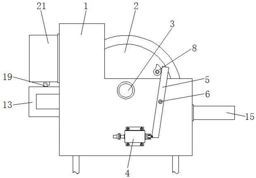
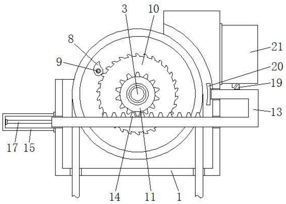
[0026] see Figure 1-5 , the present invention provides a technical solution: a speed limiting device for an elevator for electric power maintenance, including an installation box 1, a cable wheel 2 is arranged inside the installation box 1, and a main shaft 3 is installed on the cable wheel 2, and the installation box 1 An electromagnetic switch 4 is provided on the outside of the electromagnetic switch 4, and the outside of the electromagnetic ...


PUM


Abstract

The invention discloses a speed-limiting device for a lift used for electric power maintenance, which comprises an installation box, a cable wheel is arranged inside the installation box, a main shaft is installed on the cable wheel, an electromagnetic switch is arranged outside the installation box, And the outside of the electromagnetic switch is connected with a driving rod, the driving rod is located outside the installation box, and the first horizontal shaft is installed on the driving rod, the upper surface of the brake rod is provided with a trigger block, and the other end of the brake rod is installed There is a brake plate, and the brake plate is located between the cable wheel and the installation box, a micro switch is arranged above the trigger block, and the micro switch is installed on the outer surface of the installation box. In the elevator speed limiting device for electric power maintenance, after the electromagnetic switch stops working, the vortex spring pushes the drive rod to rotate on the first horizontal axis, which is convenient for the drive rod to push and move the ratchet, so the ratchet will rotate. It is beneficial for the connection between the ratchet and the ratchet, so it is convenient to trigger and drive the subsequent related structures.

Description

technical field [0001] The invention relates to the technical field of electric power maintenance, in particular to an elevator speed limiting device for electric power maintenance. Background technique [0002] The power supply system is composed of power equipment, cables, and support rods. When the high-altitude power supply equipment fails, it is often necessary to perform maintenance on the high-altitude power supply. In order to facilitate the maintenance of high-altitude power equipment, workers usually need to use elevators, etc. The equipment carries out climbing work, which is convenient for workers to reach the corresponding height for maintenance and maintenance of related equipment. However, the existing winder device usually has the following problems in the process of use: [0003] 1. When the driving wire wheel of the elevator runs at overspeed, it is easy to affect the stability of the traction of the lifting platform, which may easily cause the relevant per...

Claims


Application Information

Patent Timeline
Patent Type & Authority Patents(China)
IPC IPC(8): B66F17/00B66F11/00B66F13/00B66D5/08B66D5/24
CPCB66F17/006B66F11/00B66F13/00B66D5/08B66D5/24Y02B50/00
Inventor 陈建宝宁波史册陈大军熊卫明
Owner 国网湖北省电力有限公司直流公司
Why Eureka
Try Eureka