
Dust removal and denitration method

A denitrification and square technology, applied in separation methods, chemical instruments and methods, dispersed particle filtration, etc., can solve problems such as waste, blockage of screen meshes, and primary filtration of smoke and dust affecting flue gas transportation, so as to improve the utilization rate, The effect of reducing waste

Active Publication Date: 2020-10-16
CHONGQING YUANDA CATALYST MFG
View PDF7 Cites 2 Cited by
  • Summary
  • Abstract
  • Description
  • Claims
  • Application Information

AI Technical Summary

Problems solved by technology

[0005] In order to solve the above-mentioned technical problems, the present invention provides a dust removal and denitrification method to solve the problem that in the current dust removal and denitrification method, the dust contained in the flue gas is generally firstly filtered through the filter plate, followed by The final dust removal operation is carried out on the flue gas through filtering equipment such as metal fiber filter bags, but after a short period of use of the filter plate used for the primary filtering operation, the smoke and dust filtered on the filter plate can easily cause the mesh of the filter plate to be damaged. The blockage affects the transportation of flue gas and the primary filtration of the flue dust contained in it; the current dust removal and denitrification method generally uses a denitrification catalyst to denitrify the flue gas. The denitration coefficient of the contact end of the gas will gradually decrease, which will gradually affect the overall denitration coefficient of the denitration catalyst. Therefore, when the denitration coefficient of the first contact end of the denitration catalyst and flue gas will gradually decrease or become invalid, a new denitration catalyst needs to be replaced. The other half of the original denitrification catalyst can still be used normally, causing a huge waste of problems

Method used


Image

  • Dust removal and denitration method
  • Dust removal and denitration method
  • Dust removal and denitration method

Examples


Embodiment

[0035] as attached figure 1 to attach Figure 9 Shown:

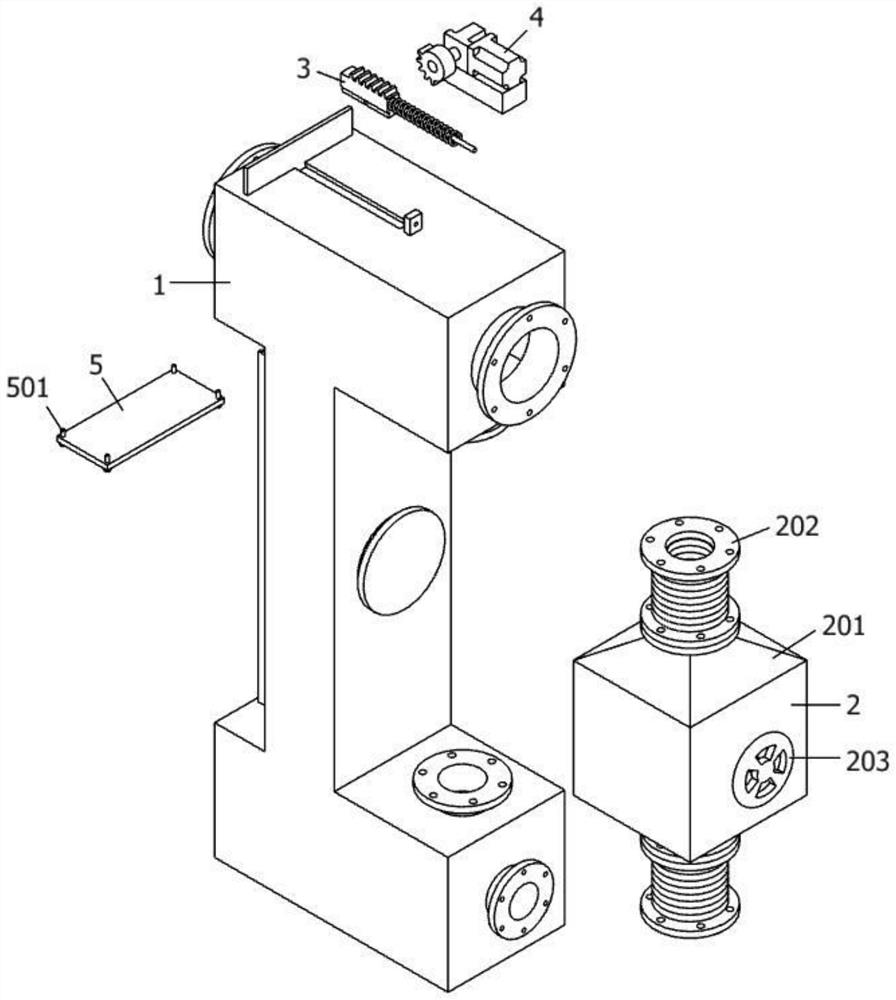
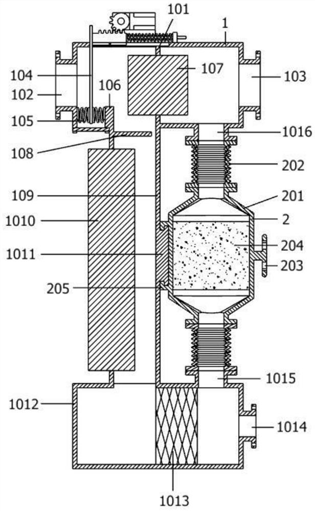
[0036] The present invention provides a dust removal and denitrification method. The method realizes dust removal and denitrification through an integrated dust removal and denitrification device equipped with an upper rectangular housing 1, a square housing 2, an intermittent dust removal mechanism 3, a driving mechanism 4, and a rectangular plate 5;

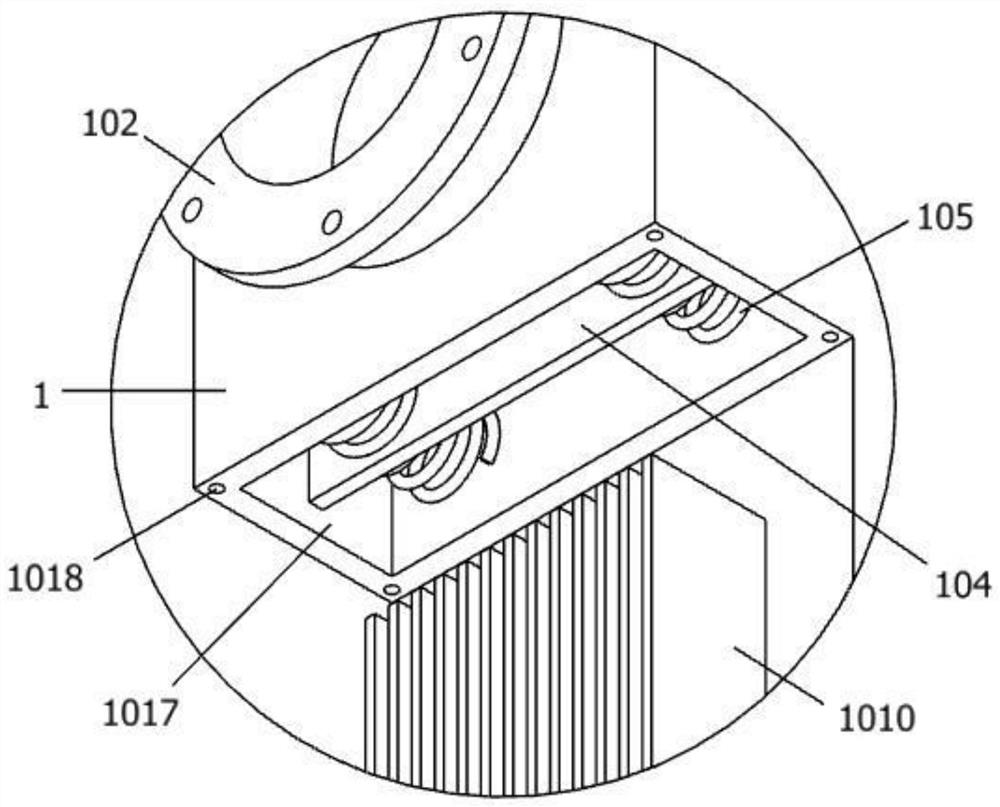
[0037] The dust removal and denitrification integrated equipment includes: an upper rectangular housing 1, a square housing 2 is arranged on the lower right side of the upper rectangular housing 1; an intermittent dust cleaning mechanism is installed slidingly on the left side of the top surface of the upper rectangular housing 1 3. On the left side of the top surface of the upper rectangular housing 1, a driving mechanism 4 is fixedly installed in engagement with the intermittent dust cleaning mechanism 3; on the left side of the bottom surface of the upper rectangular ...


PUM


Abstract

The invention provides a dust removal and denitration method, and relates to the technical field of flue gas treatment. The method realizes dust removal and denitration by dust removal and denitrationintegrated equipment provided with an upper rectangular shell, a square shell, an intermittent ash removal mechanism, a driving mechanism and a rectangular plate. In the prior art, a denitration catalyst is used in flue gas denitration treatment, after long time denitration, the denitration coefficient of the end that contacts flue gas firstly decreases gradually, the overall denitration coefficient of the denitration catalyst is gradually influenced, the denitration catalyst should be replaced, and the denitration catalyst is wasted, and the provided method solves the problems mentioned above.

Description

technical field [0001] The invention belongs to the technical field of flue gas treatment, and more specifically relates to a dust removal and denitrification method. Background technique [0002] High-temperature industrial flue gas contains a large amount of available energy and substances, and its rational use has huge economic and social benefits. Realizing high-temperature flue gas dust removal is a key technology to achieve energy conservation and emission reduction goals and improve the comprehensive utilization of resources. Traditional high-temperature Dust removal treatment and denitrification treatment of flue gas need to be treated separately, which requires a large amount of catalyst and a large amount of hazardous waste, and high dust denitrification has problems such as blockage, wear, poisoning, and ammonia escape. In view of this, it is necessary to study a high-temperature Ultra-clean dust removal and denitrification method. [0003] For example, applicati...

Claims


Application Information

Patent Timeline
Patent Type & Authority Applications(China)
IPC IPC(8): B01D46/00B01D46/42B01D53/88B01D53/56
CPCB01D46/4218B01D53/8631B01D53/885B01D2258/0283B01D2267/40B01D46/76B01D46/62
Inventor 张海波
Owner CHONGQING YUANDA CATALYST MFG
Learn More