
Extra-high voltage multi-terminal hybrid direct-current power transmission system valve group fault exit control method

A hybrid DC and power transmission system technology, which is applied to electrical components, emergency protection circuit devices, etc., can solve the problems of being unable to adapt to the UHV flexible DC transmission system and the UHV multi-terminal hybrid DC transmission system, so as to reduce the scope of fault influence , stable change and small impact

Pending Publication Date: 2020-10-13
BEIJING SIFANG JIBAO AUTOMATION +1
View PDF3 Cites 2 Cited by
  • Summary
  • Abstract
  • Description
  • Claims
  • Application Information

AI Technical Summary

Problems solved by technology

However, the existing UHV DC transmission projects all use conventional DC converter stations, and the existing control strategy for converter valve failure exit is only applicable to conventional HVDC transmission systems at both ends of UHV, and cannot be adapted to UHV flexible DC transmission systems. It is not suitable for UHV multi-terminal hybrid DC transmission system

Method used


Image

  • Extra-high voltage multi-terminal hybrid direct-current power transmission system valve group fault exit control method
  • Extra-high voltage multi-terminal hybrid direct-current power transmission system valve group fault exit control method
  • Extra-high voltage multi-terminal hybrid direct-current power transmission system valve group fault exit control method

Examples


Embodiment Construction

[0039] The application will be further described below in conjunction with the accompanying drawings. The following examples are only used to illustrate the technical solutions of the present invention more clearly, but not to limit the protection scope of the present application.

[0040] The UHV multi-terminal hybrid direct current transmission system has multiple operation modes and multiple applicable control strategies. For the convenience of subsequent description, the present invention selects one of the typical topologies as an embodiment for description.

[0041] In this technical field, the conventional converter station is referred to as the LCC converter station for short, and the flexible DC converter station is referred to as the MMC converter station; at present, when the flexible DC converter station is applied to the UHV DC transmission system, a certain number of full bridges must be used modules to deal with the special working conditions of UHV. For the con...


PUM


Abstract

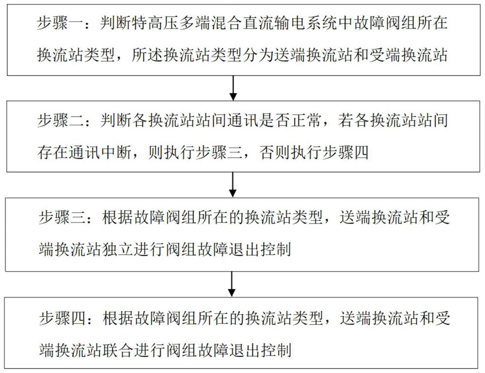
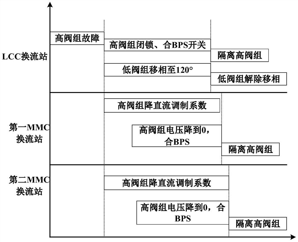
The invention discloses an extra-high voltage multi-terminal hybrid direct-current power transmission system valve group fault exit control method. The method comprises the steps of judging the typesof converter stations where a fault valve group is located in an extra-high voltage multi-terminal hybrid direct-current power transmission system, wherein the types of the converter stations are divided into a sending-end converter station and a receiving-end converter station; judging whether the inter-station communication of the converter stations is normal or not, and if the inter-station communication of the converter stations is interrupted, independently carrying out valve group fault quit control according to the type of the converter station where the fault valve group is located, the sending-end converter station and the receiving-end converter station; otherwise, according to the type of the converter station where the fault valve group is located, allowing the sending-end converter station and the receiving-end converter station to jointly carry out valve group fault quit control. The method is suitable for the multi-terminal hybrid direct-current power transmission control system, the control characteristics of different types of valve groups are combined, the valve groups of all stations are matched with one another, the fault quitting of the valve groups of the multi-terminal hybrid direct-current power transmission system can be rapidly completed, and the shutdown of the whole system caused by faults of a single valve group is avoided.

Description

technical field [0001] The invention belongs to the technical field of UHV multi-terminal hybrid direct current transmission system control, and relates to a method for controlling failure exit of a valve group of an UHV multi-terminal hybrid direct current transmission system. Background technique [0002] The conventional DC transmission system has the advantages of large transmission capacity, high voltage level, low manufacturing cost, low operating loss, and mature and reliable technology. This transmission method has good technical and economical efficiency when transmitting electric energy with large capacity and long distances. But at the same time, it has the disadvantages of needing a large number of filtering and reactive power compensation devices, and easy commutation failure when used as an inverter station. [0003] Flexible DC transmission system has the advantages of good control performance, flexible operation mode, no need for reactive power compensation, ...

Claims


Application Information

Patent Timeline
IPC IPC(8): H02H7/26
CPCH02H7/268
Inventor 刘静佳梅红明刘树于华龙
Owner BEIJING SIFANG JIBAO AUTOMATION
Learn More