Bragg grating and its preparation method, distributed feedback laser

A Bragg grating and distributed feedback technology, which is applied in lasers, semiconductor lasers, phonon exciters, etc., can solve the problems of reduced refractive index of coupling coefficient, narrow response bandwidth of small signal intensity modulation, unfavorable high-speed direct modulation, etc.

Active Publication Date: 2021-09-21
泉州市三安光通讯科技有限公司
View PDF10 Cites 0 Cited by
  • Summary
  • Abstract
  • Description
  • Claims
  • Application Information

AI Technical Summary

Problems solved by technology

[0003] In the current distributed feedback semiconductor laser, the conventional grating design makes the increase of the injection current cause the decrease of its coupling coefficient (because when the carriers flow through the narrow bandgap material, according to the Kramers-Kronig relationship, the refractive index will be higher than that of the wide bandgap material There is a larger drop, so that the increase of the injection current will reduce the refractive index difference of the grating), and the drop of the grating coupling coefficient will cause the distribution feedback in the optical cavity to decrease, which will lead to an increase in the cavity loss. Such a differential cavity loss is a positive value, that is, its differential net gain is low, so its relaxation oscillation frequency will decrease accordingly, making its small signal intensity modulation response bandwidth narrower, which is not conducive to high-speed direct modulation

Method used


Image

  • Bragg grating and its preparation method, distributed feedback laser
  • Bragg grating and its preparation method, distributed feedback laser
  • Bragg grating and its preparation method, distributed feedback laser

Examples


Embodiment Construction

[0032] In order to make the purpose, technical solutions and advantages of the embodiments of the present invention clearer, the technical solutions in the embodiments of the present invention will be clearly and completely described below in conjunction with the drawings in the embodiments of the present invention. Obviously, the described embodiments It is a part of embodiments of the present invention, but not all embodiments. The components of the embodiments of the invention generally described and illustrated in the figures herein may be arranged and designed in a variety of different configurations.

[0033] Accordingly, the following detailed description of the embodiments of the invention provided in the accompanying drawings is not intended to limit the scope of the claimed invention, but merely represents selected embodiments of the invention. Based on the embodiments of the present invention, all other embodiments obtained by persons of ordinary skill in the art wi...


PUM

PropertyMeasurementUnit
thicknessaaaaaaaaaa

Abstract

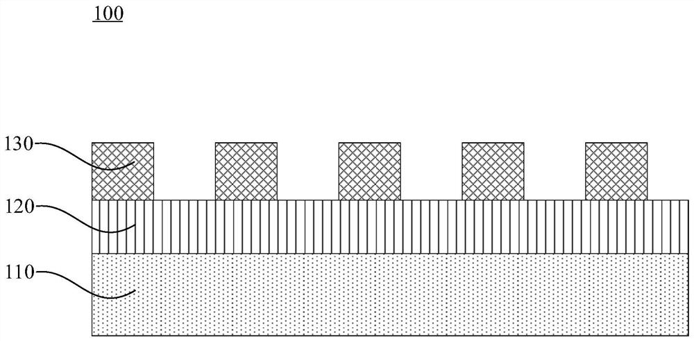
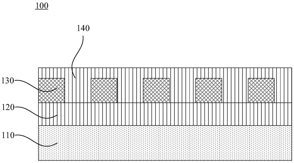
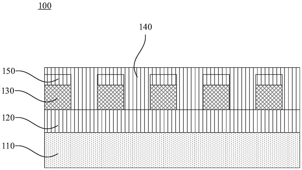
The invention provides a Bragg grating, a preparation method thereof, and a distributed feedback laser, belonging to the technical field of semiconductor lasers. The Bragg grating is set in the distributed feedback laser, including: the lower grating waveguide layer, the middle grating waveguide layer and the upper grating waveguide layer with different refractive indices formed in sequence, the refractive index of the middle grating waveguide layer is lower than that of the lower grating waveguide layer The refractive index and the refractive index of the upper grating waveguide layer, the doping type of the lower grating waveguide layer and the middle grating waveguide layer are the same, and the doping type of the upper grating waveguide layer is opposite to that of the adjacent layer, which is used for the upper grating waveguide The layers form a reverse-biased PN junction, and the upper grating waveguide layer is formed with a plurality of grooves at intervals along the cavity length direction of the distributed feedback laser, and the grooves are filled with buried layers to flatten the upper grating waveguide layer. The coupling coefficient of the Bragg grating can increase as the current of the distributed feedback laser increases, thereby reducing the cavity loss of the distributed feedback laser and expanding the response bandwidth.

Description

technical field [0001] The invention relates to the technical field of semiconductor lasers, in particular to a Bragg grating, a preparation method thereof, and a distributed feedback laser. Background technique [0002] With the development of data centers and optical fiber access networks, there is an increasing demand for low-cost, high-bit-rate communication systems. In order to reduce the cost as much as possible, direct modulation semiconductor lasers (usually distributed feedback lasers) are generally used as light sources in such systems to save the additional complexity and corresponding costs brought about by external modulators. [0003] In the current distributed feedback semiconductor laser, the conventional grating design makes the increase of the injection current cause the decrease of its coupling coefficient (because when the carriers flow through the narrow bandgap material, according to the Kramers-Kronig relationship, the refractive index will be higher t...

Claims


Application Information

Patent Timeline
Patent Type & Authority Patents(China)
IPC IPC(8): H01S5/12H01S5/22
CPCH01S5/1228H01S5/2202H01S5/1231H01S5/209H01S5/2031H01S5/3235H01S5/1234H01S5/305
Inventor 孙维忠赵桑之李洵
Owner 泉州市三安光通讯科技有限公司
Why Eureka
Try Eureka