


Quick Research
Generate reliable direction feasibility study reports for your R&D in just a few steps.

Technical Q&A
Discover and master advanced knowledge NOW. Basics, ideas, possibilities, all at once.

Find Solutions
As an expert in R&D theories, this can generate solutions to your technical problems instantly.

Evaluate Feasibility
Analyze your overall solution with one click, know your potential R&D risks in advance.

Monitor Landscape
Get weekly tech updates, stay abreast of the latest tech innovations and key insights.
Segmented bent cap dry-connection installation system and assembly construction method of bridge
A technology of installation system and construction method, which is applied in the direction of erecting/assembling bridges, bridges, bridge parts, etc., can solve the problems of difficult positioning and matching, and achieve the effects of low safety risk, short lifting time and high splicing efficiency
- Summary
- Abstract
- Description
- Claims
- Application Information
AI Technical Summary
Problems solved by technology
Method used
Image

Examples
no. 1 example
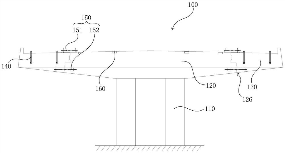
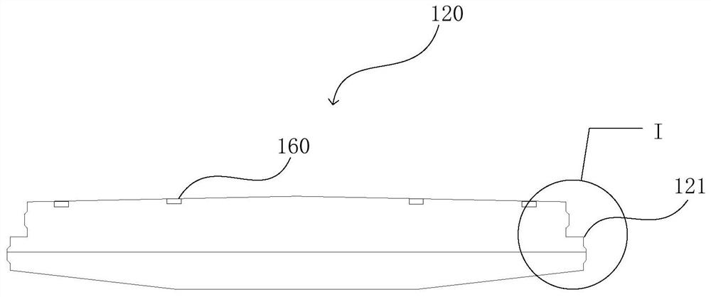
[0041] see figure 1, which is a schematic elevation view of a segmented cover beam dry joint installation system 100 provided in an embodiment of the present invention. The segmented cover beam dry joint installation system 100 includes, for example: a plurality of columns 110 , The main cover beam section 120 and the two cover beam cantilever sections 130 respectively connected to the two sides of the main cover beam section 120 . Wherein, the plurality of upright columns 110 are arranged vertically on the ground in at least two rows, and the cover beam main section 120 is arranged on the top of the plurality of upright columns 110 .
[0042] Preferably, each cover beam cantilever section 130 is respectively provided with at least one suspension point 140, and vertically connects the side of the cover beam cantilever section 130 close to the column 110, for the cover beam cantilever section 130 and the cantilever beam Connection. For example, each cover beam cantilever segm...
no. 2 example
[0058] see Figure 6 , which is a schematic flow chart of the construction method for the dry joint installation of segmented cap beams provided in the second embodiment of the present invention; including:
[0059] Step S1, prefabricating the main section 120 of the cover beam and the two matching cantilever sections 130 of the cover beam;
[0060] Step S2, installing the cap beam main section 120 to the top ends of at least two columns 110 at predetermined positions;
[0061] Step S3, arranging a plurality of pad beams 200 on the cover beam main section 120 and locking the distribution beam 180;
[0062] Step S4, apply epoxy resin glue layer 126 on the two sides of the main cover beam section 120 respectively, and hang the two cantilever sections 130 of the cover beam on both sides of the main cover beam section 120 through the distribution beam 180;
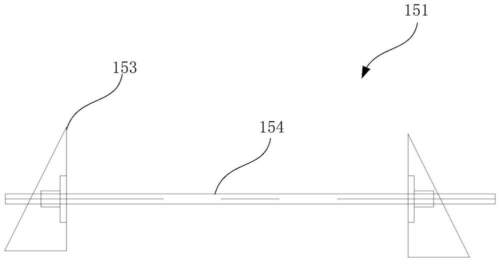
[0063] Step S5, tensioning the tensioning device 150 connected between the main section 120 of the cover beam and the cant...
PUM
 Abstract
Description
Claims
Application Information
 - R&D Engineer
- R&D Manager
- IP Professional
- Industry Leading Data Capabilities
- Powerful AI technology
- Patent DNA Extraction
Browse by: Latest US Patents, China's latest patents, Technical Efficacy Thesaurus, Application Domain, Technology Topic, Popular Technical Reports.
© 2024 PatSnap. All rights reserved.Legal|Privacy policy|Modern Slavery Act Transparency Statement|Sitemap|About US| Contact US: help@patsnap.com