Anti-slip cushion pad

A technology of anti-slip cushioning and split body, which is applied to floors, carpets, elastic floors, etc., can solve the problems of limited impact absorption function, and achieve the effect of easy manufacturing and reduced manufacturing cost

Inactive Publication Date: 2020-10-13
智慧头脑有限公司
View PDF7 Cites 0 Cited by
  • Summary
  • Abstract
  • Description
  • Claims
  • Application Information

AI Technical Summary

Problems solved by technology

The part corresponding to the anti-slip unit is constructed to form a drainage channel in the form of a relatively protruding cross, and can be combined in various forms according to the installation site and drain water smoothly, although it is suitable for use in a bathroom or a place with water, it is shock-absorbing limited functionality
[0006] The "connection structure of children's safety mats installed on the roof of a building" is constructed by combining a plurality of sound-insulating mats and a plurality of safety mats formed with concave-convex anti-slip units. By combining the sound-insulating mats The method of soft mats and safety mats can be easily combined and set up, and some damaged mats can be easily replaced and repaired, however, two kinds of mats must be combined to perform multiple functions, and it is necessary to use the integrated type at the desired position limited
[0007] The "ceramic-coated rubber floor mat for preventing conveyor pulleys from slipping and its manufacturing method" is composed of rubber floor mats, anti-slip protrusion units and ceramic tiles, which increase the distance between the conveyor belt and the rotating drum or conveyor pulley. Static friction to prevent conveyor pulleys from idling, and stable operation even when subjected to external influences such as snow and rain, however, there are limitations in bonding to floor mats due to fixing methods and surface conditions, and suitable combination deformation to all range is limited

Method used


Image

  • Anti-slip cushion pad
  • Anti-slip cushion pad
  • Anti-slip cushion pad

Examples


Embodiment Construction

[0030] Hereinafter, the present disclosure will be described with reference to the accompanying drawings. In the following description of the present disclosure, when it is judged that the detailed description of related technologies or structures may unnecessarily obscure the gist of the present disclosure, the detailed description thereof will be omitted.

[0031] The terms used below are terms defined in consideration of the functions of the present disclosure, which may vary according to users' and operators' intentions or habits, and thus, the definitions of the terms should be based on the descriptions throughout the specification describing the present disclosure.

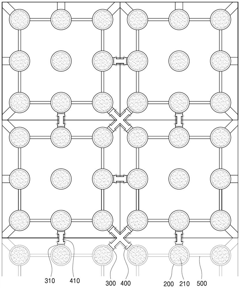
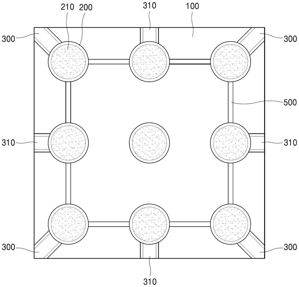
[0032] The anti-slip cushion according to an embodiment of the present disclosure may be as figure 1 and figure 2 Use the combinations shown. refer to Figure 3 to Figure 7 , The anti-slip cushion according to the embodiment of the present disclosure may include a cushion split body 100 , an insertion po...


PUM


Abstract

The present disclosure relates to an anti-slip cushion pad comprising a pad split body having a quadrangular shape; a plurality of insertion openings formed in the bottom surface of the pad split bodyand made of a hard resin material; a buffer gel attached to the bottom surfaces of the plurality of insertion openings; a plurality of main connecting grooves which are formed by recessing from the corners of the bottom surface of the pad division body to the inner side direction in an inclined manner; and a main connection groove fixing piece which has a cross shape and is fixed in the main connection grooves of the four pad split bodies which are adjacently connected based on each corner of the pad split bodies in an interference fit manner, and the anti-skid cushion pad is used according to the area combination and connection of the floor, and can prevent impact and skid at the same time.

Description

technical field [0001] The present disclosure relates to a non-slip cushion. Specifically, it relates to a non-slip cushion that is inserted into the bottom surface of a soft mat segment to form a hard insertion opening, and prevents slippage by cushion gel attached to the bottom surface of the insertion opening. In addition, it relates to a non-slip cushioning pad, which can easily lay an anti-slip cushioning pad suitable for a required area in a combined pad split body through the connection structure of the fixing pieces fixed to the connection grooves of the adjacent pad split bodies. . Background technique [0002] Various mats and pads are used in real life. In particular, since floor mats such as kitchen mats, sports mats, game room mats, etc. pose a risk of serious injury to users when slipping on the floor, an anti-slip function has become an important requirement. [0003] In addition, recently, in addition to various child-related facilities such as nursery sch...

Claims


Application Information

Patent Timeline
Patent Type & Authority Applications(China)
IPC IPC(8): A47G27/02E04F15/22
CPCA47G27/0212A47G27/0218E04F15/22E04F15/02005E04F15/02172E04F15/105
Inventor 孙庆睦
Owner 智慧头脑有限公司
Why Eureka
Try Eureka