Anti-shaking stacking machine
A stacker, main body technology, applied in conveyors, mechanical equipment, engine components, etc., can solve the problems of inability to install lubricating operations, reduce work stability performance, and small supporting strength, achieve not easy to jam, better effect, increase The effect of using performance
- Summary
- Abstract
- Description
- Claims
- Application Information
AI Technical Summary
Problems solved by technology
Method used
Image

Examples
Embodiment 1
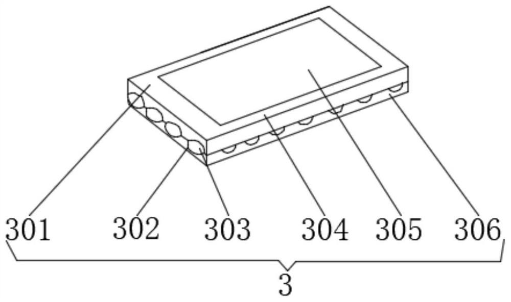
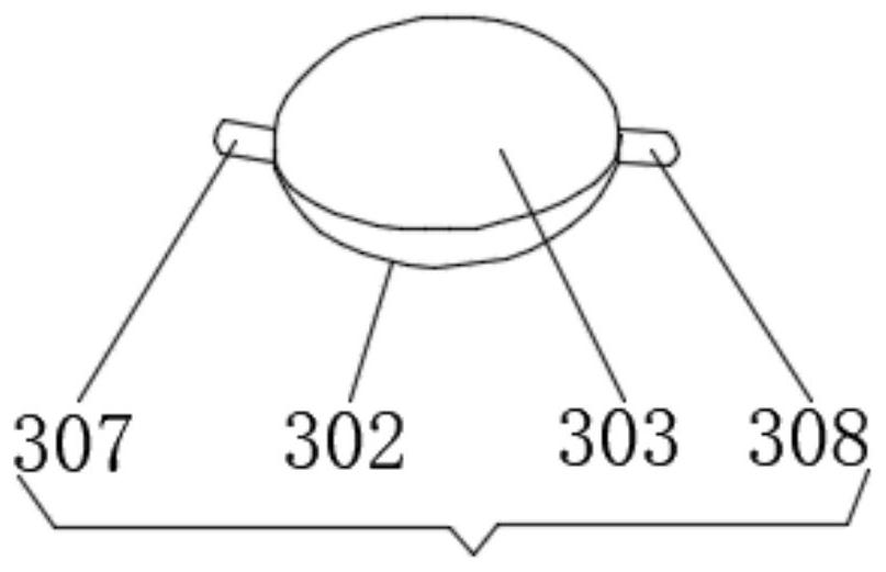
[0030] Embodiment 1: Load-bearing roller base mechanism 3 includes load-bearing seat 301, anti-skid pad 302, roller 303, wear-resistant pad 304, weighing mechanism 305, dust cover 306, No. 1 roller 307, No. 2 roller 308, wear-resistant Pad 304 is located on the outer surface of the upper end of bearing seat 301, weighing mechanism 305 is located in the inside of bearing seat 301, No. 1 roller 307 and No. The outer wall of the second roller 308, the anti-slip pad 302 is located on the outer surface of the roller 303, the dust cover 306 is located around the bearing seat 301, and the inner wall of the roller 303 passes through the contact between the first roller 307, the second roller 308 and the bearing seat 301. The inner side of the lower end is movably connected, and an installation card slot is provided between the load-bearing seat 301 and the weighing mechanism 305. The inside of the load-bearing seat 301 is detachably connected to the outside of the weighing mechanism 30...
Embodiment 2
[0031]Embodiment 2: The positioning protection rod mechanism 4 includes a protection plate 401, a positioning plate 402, a support rod 403, a positioning base 404, a positioning pin 405, and a protection pad 406. The positioning pin 405 is located at the four corners of the positioning base 404, and the support rod 403 is located at the positioning base. 404, the positioning plate 402 is located at one end of the support rod 403, the protective plate 401 is located at one side of the positioning plate 402, the protective pad 406 is located at the inner surface of the protective plate 401, and the rear end outer surface of the protective plate 401 is connected to the support by the positioning plate 402. The outer surface of the front end of the rod 403 is fixedly connected, and a welding seat is arranged between the supporting rod 403 and the positioning base 404. The outer surface of the lower end of the supporting rod 403 is fixedly connected with the upper end outer surface o...
Embodiment 3
[0032] Embodiment 3: The sliding seat mechanism 5 includes a lubricating box 501, a slide rail 502, a telescopic plate 503, a lubricating groove 504, an oil inlet 505, and an oil outlet 506. The slide rail 502 is located at the rear end of the lubricating box 501, and the oil outlet The port 506 is located inside the slide rail 502, the lubricating groove 504 is located at the upper end of the lubricating box 501, the telescopic plate 503 is located inside the lubricating groove 504, the oil inlet 505 is located inside the lubricating groove 504, and the telescopic plate 503 and the lubricating groove 504 are arranged There is a chute, the inner side of the lubricating groove 504 is movably connected with the two sides of the telescopic plate 503 through the chute, a fixed block is arranged between the lubricating box 501 and the slide rail 502, and the outer surface of the front end of the lubricating box 501 is connected to the slide rail 502 through the fixed block. The oute...
PUM
 Abstract
Description
Claims
Application Information
 - Generate Ideas
- Intellectual Property
- Life Sciences
- Materials
- Tech Scout
- Unparalleled Data Quality
- Higher Quality Content
- 60% Fewer Hallucinations
Browse by: Latest US Patents, China's latest patents, Technical Efficacy Thesaurus, Application Domain, Technology Topic, Popular Technical Reports.
© 2025 PatSnap. All rights reserved.Legal|Privacy policy|Modern Slavery Act Transparency Statement|Sitemap|About US| Contact US: help@patsnap.com