
A stainless steel pipe automatic welding process

An automatic welding and stainless steel pipe technology, applied in welding equipment, welding equipment, auxiliary welding equipment, etc., can solve the problem of affecting the connection strength of the welded product, the appearance and appearance, the inconvenience of quick docking of stainless steel pipe welding ports, and the difficulty of ensuring that the ports are tightly fitted Accuracy and other issues, to achieve the effect of ensuring welding strength and welding aesthetics, ensuring accuracy and butt tightness, and precise butt jointing

Active Publication Date: 2021-05-11
徐州同乐管业有限公司
View PDF8 Cites 0 Cited by
  • Summary
  • Abstract
  • Description
  • Claims
  • Application Information

AI Technical Summary

Problems solved by technology

[0003] In the actual processing process, according to the actual needs of the layout of steel pipe components, it is often necessary to weld stainless steel pipes, the most common of which are straight line welding and vertical welding, where vertical welding includes the vertical welding of two stainless steel pipe ports. Welding and vertical welding of one stainless steel pipe port relative to the side wall of the other stainless steel pipe. In the process of vertical welding of two stainless steel pipe ports, it is often necessary to cut the stainless steel pipe port in advance so that the port forms a welding port slope. In the actual welding operation process, manual alignment welding is generally carried out directly. Obviously, during the operation process, it is not convenient to quickly connect the welding ports of two stainless steel pipes, and it is not easy to ensure the accuracy of the ports being tightly fitted, which affects the accuracy of the butt joint. The connection strength and appearance of the final welded product

Method used


Image

  • A stainless steel pipe automatic welding process
  • A stainless steel pipe automatic welding process
  • A stainless steel pipe automatic welding process

Examples


Embodiment Construction

[0035] The specific embodiment of the present invention will be described in further detail by describing the embodiments below with reference to the accompanying drawings, with the purpose of helping those skilled in the art to have a more complete, accurate and in-depth understanding of the concept and technical solutions of the present invention, and To facilitate its practice, but not as a limitation of the invention.

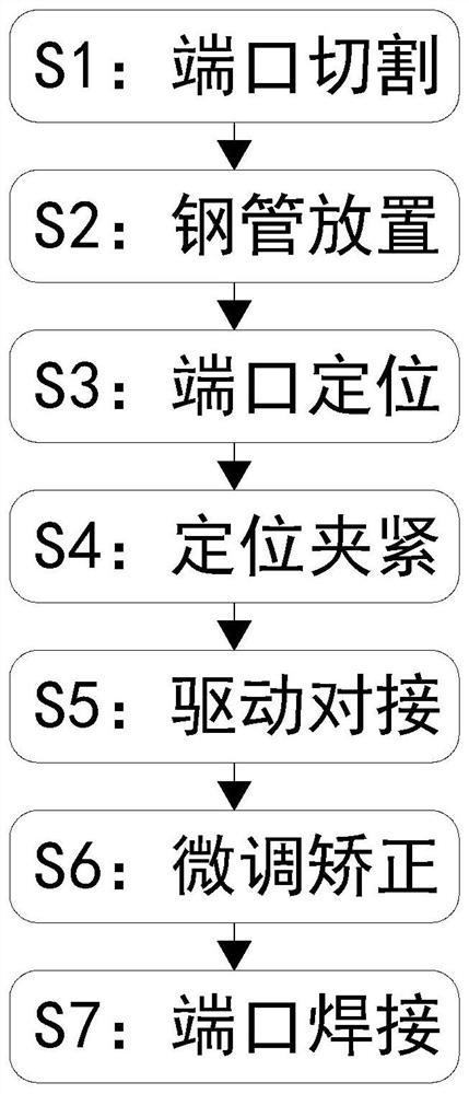
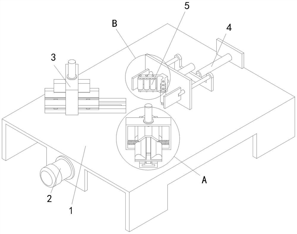
[0036] See attached Figure 1-9As shown, a stainless steel pipe automatic welding process, its welding process specifically includes the following steps:

[0037] S1. Port cutting: cutting the port at one end of the stainless steel pipe to be welded so that the port serves as a welding port;

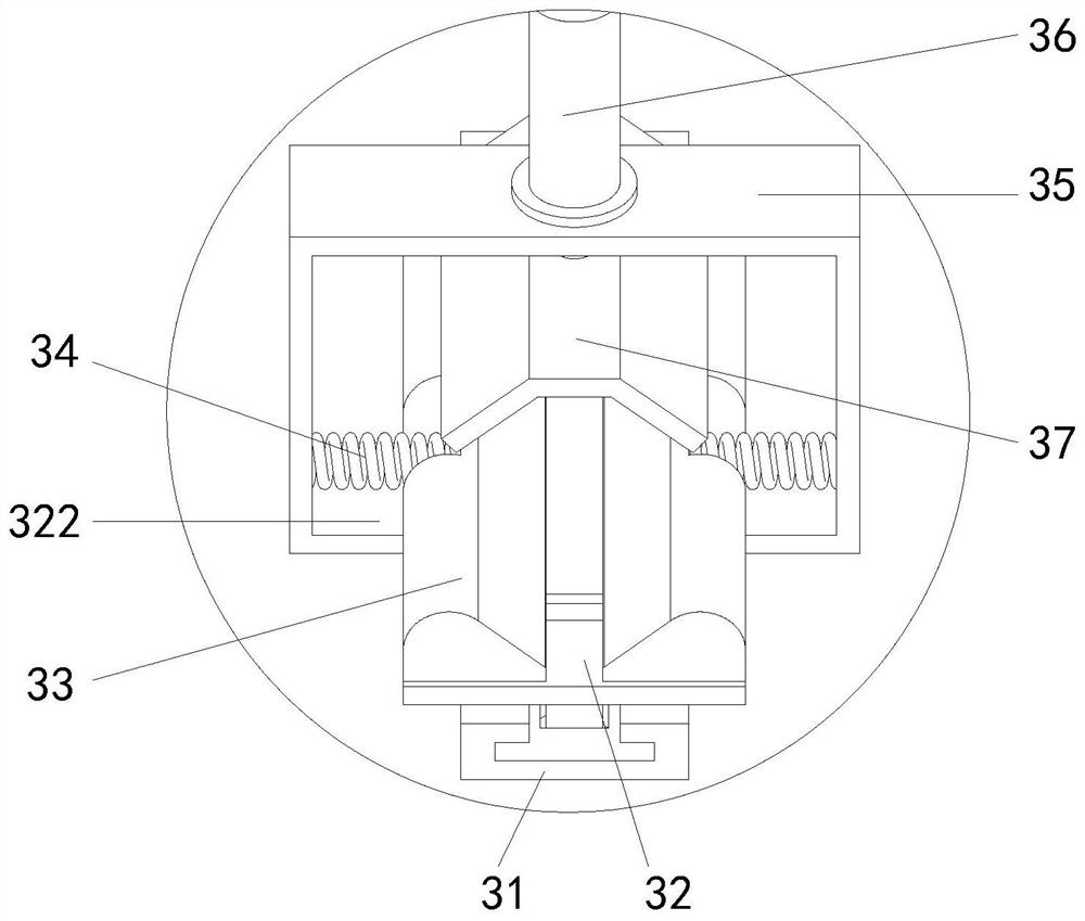
[0038] S2. Placement of the steel pipes: placing the two stainless steel pipes whose ports have been cut through the step S1 in the two positioning and clamping mechanisms 3 in one-to-one correspondence;

[0039] S3. Port positioning: the welding ports of the two st...


PUM


Abstract

The present invention relates to an automatic welding process for stainless steel pipes, in particular to an automatic welding fixture for stainless steel pipes, which includes a fixture table, a docking synchronous drive mechanism arranged under the fixture table, and two A positioning and clamping mechanism for a stainless steel pipe, a positioning baffle plate mechanism for positioning two stainless steel pipe welding ports and a fine-tuning correction mechanism for fine-tuning and correction; Welding auxiliary docking can automatically and quickly realize the precise docking of two stainless steel pipe welding ports, ensuring the accuracy and tightness of the welding port docking, and then ensuring the welding quality of the welded product, welding strength and welding aesthetics.

Description

technical field [0001] The invention relates to the technical field of welding processing, and specifically proposes an automatic welding process for stainless steel pipes. Background technique [0002] Stainless steel pipe is a hollow long round steel material, which is widely used in petroleum, chemical, medical, food, light industry, mechanical instrumentation and other industrial pipelines and mechanical structural components. At the same time, it is light in weight, so it is also widely used in the manufacture of mechanical parts and engineering structures. [0003] In the actual processing process, according to the actual needs of the layout of steel pipe components, it is often necessary to weld stainless steel pipes, the most common of which are straight line welding and vertical welding, where vertical welding includes the vertical welding of two stainless steel pipe ports. Welding and vertical welding of one stainless steel pipe port relative to the side wall of t...

Claims


Application Information

Patent Timeline
Patent Type & Authority Patents(China)
IPC IPC(8): B23K31/02B23K37/00B23K37/053
CPCB23K31/02B23K37/00B23K37/053B23K37/0533
Inventor 张景龙李翔
Owner 徐州同乐管业有限公司
Learn More