
Pipe condition control intelligent irrigation valve, irrigation system and irrigation method

A technology for intelligent control and situation management, applied in control/adjustment systems, non-electric variable control, liquid fertilizer adjustment systems, etc., can solve problems such as pipe rupture or burst, soil structure damage, low water and fertilizer utilization rate, etc., to achieve precise The effect of water and fertilizer irrigation, avoiding tube detachment or bursting, and reducing testing costs

Active Publication Date: 2020-10-09
TAIZHOU JUNGANG COPPER CO LTD
View PDF5 Cites 4 Cited by
  • Summary
  • Abstract
  • Description
  • Claims
  • Application Information

AI Technical Summary

Problems solved by technology

[0003] The existing automatic agricultural irrigation machinery, especially the automatic control of the irrigation valve, adopts the solenoid valve control, but the solenoid valve needs a certain pressure to start, and it is controlled by the switch, which can only realize the opening and closing of the valve body. , especially in drip irrigation operations, the control of pipeline pressure depends on human experience, which is very random, and there is no scientific data support in the entire irrigation process. The phenomenon of pipe rupture or pipe burst will lead to random irrigation water and fertilization, low utilization rate of water and fertilizer, serious waste of resources (the utilization rate of water and fertilizer is only about 40%), and long-term random control will cause soil structure damage and environmental pollution. agricultural planting issues

Method used


Image

  • Pipe condition control intelligent irrigation valve, irrigation system and irrigation method
  • Pipe condition control intelligent irrigation valve, irrigation system and irrigation method
  • Pipe condition control intelligent irrigation valve, irrigation system and irrigation method

Examples


Embodiment 1

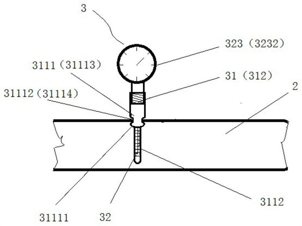
[0031] Pipe condition control intelligent irrigation valve, such as figure 1 and image 3As shown, it includes an electric valve 1, an electric valve opening control device and a pipe situation feedback system. The pipe situation feedback system includes a pipe situation detection device 3 arranged on a water belt hose 2. The pipe situation detection device 3 includes a fixed The sensor housing 31 on the water belt hose 2 and the pipe condition detection sensor 32 extending into the water belt hose 2 through the sensor housing 31; the electric valve opening control device receives the pipe After receiving the fluid information in the pipe from the condition detection sensor 32, the valve opening of the electric valve 1 is comprehensively adjusted according to the preset fluid information, and then the pipe condition feedback control between the hose 2 and the electric valve 1 is realized, and the electric valve 1 is driven. The spool of valve 1 is rotated to the appropriate v...

Embodiment 2

[0034] Different from the above-mentioned embodiments, such as figure 1 As shown, the sensor housing 31 includes a lower housing 311 and an upper housing 312 that are screwed together, and the lower housing 311 includes a pipe-through structure 3111 and a probe protection structure 3112. The probe protection structure 3112 is inserted into the water hose 2 through the side wall of the hose 2, and the sensing element of the pipe condition detection sensor 32 is placed in the filter cavity of the probe protection structure 3112. The pipe-through structure 3111 includes a lower protrusion 31111 and a sealing part 31112. The lower protrusion 31111 is located inside the hose 2 and is connected to the probe protection structure 3112. The sealing part 31112 snaps and seals the The detection hole on the side wall of hose hose 2.

[0035] Preferably, the probe protection structure 3112 includes a cylindrical shell, and the filter cavity is formed by a mesh filter or a strip filter set...

Embodiment 3

[0039] Different from the above-mentioned embodiments, such as figure 2 As shown, the sealing part 31112 includes a sealing tube external thread 31115 arranged above the lower protrusion 31111 and a sealing nut 31116 matching the sealing tube external thread 51115. The side wall of the hose 2 It is clamped between the lower protrusion 31111 and the sealing nut 31116 and seals the detection hole.

[0040] Preferably, the sealing part 31112 includes a sealing pipe external thread 31115 provided above the lower protrusion 31111 and a sealing pipe internal thread provided below the upper housing 312 , the side of the hose 2 The wall is clamped between the lower protrusion 31111 and the upper housing 312 and the detection hole is sealed by screwing the external thread 31115 of the sealing tube and the internal thread of the sealing tube.

[0041] As a preference, a threading hole 313 is provided above the upper accommodating housing 312 for the wired transmission device 3231 to t...


PUM


Abstract

The invention discloses a pipe condition control intelligent irrigation valve, an irrigation system and an irrigation method. After an electric valve opening degree control device receives in-pipe fluid information transmitted by a pipe condition detection sensor, a valve element of an electric valve is driven to rotate to the proper valve opening degree according to preset fluid information, thewater amount, pressure and flow speed in a water hose are accurately controlled, accurate water and fertilizer irrigation is achieved, the problems of pipe disengaging or pipe bursting, the water hammer phenomenon, water and fertilizer waste, water and fertilizer pipe wall corrosion and the like caused by pressure differences can be avoided, a block chain agricultural management system can be conveniently built, and intelligent agricultural management on the national scale becomes possible. A sensing element of the pipe condition detection sensor stretches into the water hose through a probe protection structure. The structure is simple and reliable, installation is convenient, on the basis of effectively obtaining the in-pipe fluid information, the sensing element is protected against impact damage, the detection cost of the intelligent irrigation system is greatly reduced, and large-area application and popularization are convenient.

Description

technical field [0001] The invention relates to the technical field of intelligent irrigation valves, in particular to an intelligent irrigation valve for condition control, an irrigation system and an irrigation method. Background technique [0002] The shortage of water resources has become a global problem. Saving water and achieving efficient water use is the need for human survival and development, as well as the needs of the global economy and society. Water resources are likely to be another scarce resource faced by human beings after petroleum resources. This is a reality that we cannot avoid. As one of the water-poor countries, our country has a large population and is in the period of economic construction and development, so the demand for water resources is increasing day by day. Since agricultural water accounts for 70% of my country's total water consumption, and the problems of low agricultural irrigation efficiency and water waste are common, the contradicti...

Claims


Application Information

Patent Timeline
IPC IPC(8): A01C23/00A01C23/04G05D27/02
CPCA01C23/007A01C23/04G05D27/02
Inventor 耿礼绍
Owner TAIZHOU JUNGANG COPPER CO LTD
Learn More