Waveguide element

A technology of waveguide components and waveguides, which is applied in the direction of optical components, light guides, planar/plate light guides, etc., can solve problems such as low-quality waveguide components and waveguide display devices, and problems caused by addition, so as to alleviate calculation problems and practical optics The effect of quality problems

Active Publication Date: 2020-10-02
DISPELIX OY
View PDF11 Cites 0 Cited by
  • Summary
  • Abstract
  • Description
  • Claims
  • Application Information

AI Technical Summary

Problems solved by technology

i.e. (nearly) perfectly coherent waves and (nearly) completely incoherent waves add relatively easily, but adding partially coherent waves where the coherence is not even fully understood can cause problems
These design and calculation related issues ultimately lead to low quality waveguide components and waveguide display devices

Method used


Image

  • Waveguide element
  • Waveguide element
  • Waveguide element

Examples


Embodiment Construction

[0013] definition

[0014] "Phase function" means as a function of the wave number in the wavelength (wave number) range of interest The phase distribution of the number.

[0015] "Geometrical optical path length" is defined herein as the distance traveled in the waveguide multiplied by the real part of the refractive index of the waveguide material at the wavelength of interest.

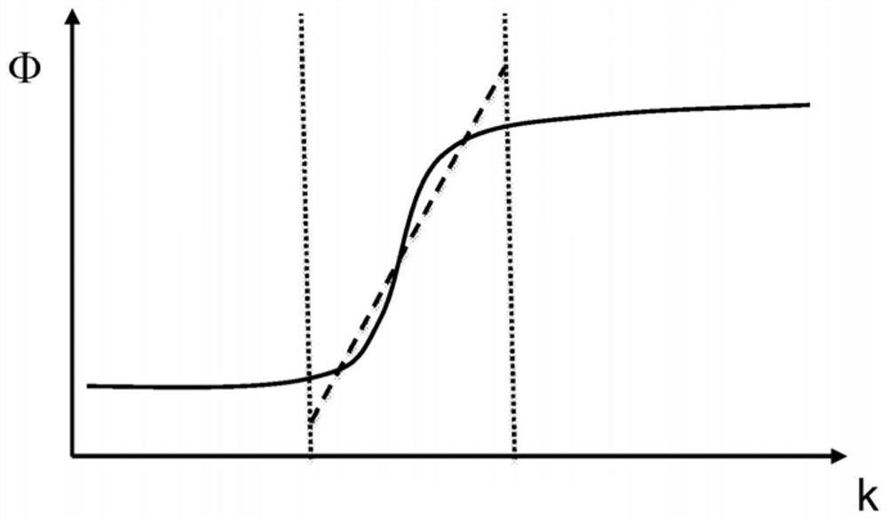
[0016] "Physical optical path length" is defined as the slope that linearly approximates the phase function at the wavelength of interest. That is, as the ratio between the phase change and the wave number difference. We note that this approximation is only used to simplify the discussion and does not mean that the phase function is or should be linear or approximately linear.

[0017] The terms "incoherent" and "fully incoherent" describe two light rays whose path length difference exceeds the coherent length in the relevant waveguide material. Specifically, if the slope of the linear approximation to...


PUM


Abstract

The invention provides a waveguide element comprising a waveguide (100) capable of guiding light rays in two dimensions via total internal reflections, and a diffractive optical element (DOE) (120) arranged on or within the waveguide (100), wherein the diffractive optical element (120) is adapted to allow propagation of light rays inside the waveguide (100) along the two dimensions so that the light rays can propagate at least from one first location (140) of the diffractive optical element (120) to at least one second location (150) of the DOE (120) along different routes (160A, 160B) havingthe same geometrical optical path length. The DOE (120) is further adapted so that at least for one wavelength range the difference in physical optical path lengths for light rays having propagated along the different routes (160A, 160B) is longer than the coherence length, so that the rays sum incoherently at the second location (150).

Description

Technical field [0001] The present invention relates to a display element based on a waveguide. Specifically, the present invention relates to a waveguide including a novel diffractive optical element. The present invention can be used in modern personal displays, such as head-mounted displays (HMD) and head-up displays (HUD). Background technique [0002] HMD and HUD can be implemented using waveguides. Diffraction gratings can be used to couple light into the waveguide, redirect into the waveguide, or couple out of the waveguide and into the user's eye. A grating in which light bounces in two dimensions can be used to perform exit pupil expansion in the waveguide, thereby effectively spreading the light field to a larger area. At each position of the grating, light waves traveling along different paths are added. Due to manufacturing-related errors, the simulated wave with zero optical path difference actually undergoes a different phase shift, making the wave partially coh...

Claims


Application Information

Patent Timeline
Patent Type & Authority Applications(China)
IPC IPC(8): G02B27/01G02B27/00G02B27/42G02B5/18G02B6/00G02F1/01
CPCG02B6/00G02F1/01G02B27/4272G02B27/0172G02B27/0081G02B5/1861G02B2027/0174G02B2027/0123G02B2027/0125G02B5/1814G02B6/0016G02B6/0038G02B27/0103G02B27/42G02F1/011G02B27/0101G02B6/0036G02B27/4233
Inventor 卡西米尔·布卢姆斯泰特伊斯莫·瓦尔蒂艾宁
Owner DISPELIX OY
Why Eureka
Try Eureka