
Electric power monitoring system and monitoring method

A technology of power monitoring and power equipment, applied in the field of electric power, can solve the problems of affecting the safety of the power grid, reducing reliability, and difficult implementation, so as to ensure safe operation, overcome poor reliability, and low implementation difficulty.

Pending Publication Date: 2020-10-02
NANJING ZHIJIN TECH INNOVATION SERVICE CENT
View PDF0 Cites 0 Cited by
  • Summary
  • Abstract
  • Description
  • Claims
  • Application Information

AI Technical Summary

Problems solved by technology

[0003] The traditional power monitoring system is equipped with a server and a power monitoring terminal for monitoring power equipment. The monitoring terminal is connected to the server in a wired manner, which has high reliability, but a large number of cables need to be laid, and the implementation cost is high. In the power system Under the influence of external factors such as the terrain of the location, the implementation is also more difficult
[0004] In the prior art, some wirelessly connected power monitoring systems have appeared. The monitoring terminals in these systems are connected to the server in a wireless manner, which avoids the laying of a large number of cables and effectively reduces the implementation cost and implementation difficulty. However, the monitoring terminals and The wireless communication signals between servers are prone to communication failure due to external interference or network congestion, resulting in a decrease in the overall reliability of the system, affecting the real-time monitoring of power equipment, and thus affecting the security of the power grid

Method used


Image

  • Electric power monitoring system and monitoring method
  • Electric power monitoring system and monitoring method

Examples


Embodiment Construction

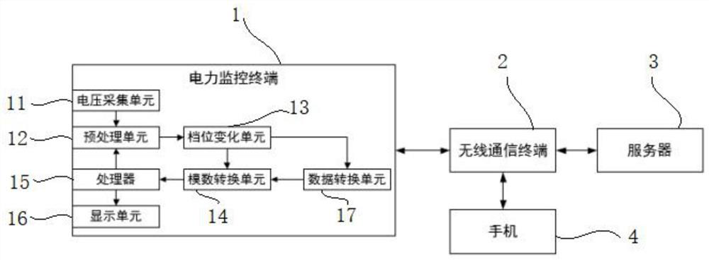
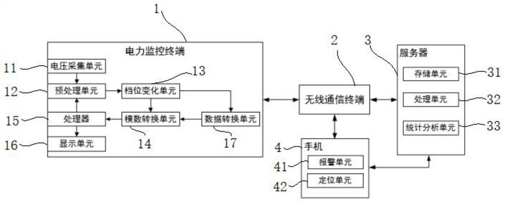
[0018] In order to make the technical means, inventive features, goals and effects achieved by the application easy to understand, the application will be further elaborated below in conjunction with specific illustrations.

[0019] It should be noted that the structures, proportions, sizes, etc. shown in the drawings attached to this specification are only used to match the content disclosed in the specification, for those who are familiar with this technology to understand and read, and are not used to limit the implementation of this application. Limiting conditions, so it has no technical substantive meaning, any modification of structure, change of proportional relationship or adjustment of size, without affecting the effect and purpose of this application, should still fall within the scope of this application. The disclosed technical content must be within the scope covered.

[0020] At the same time, terms such as "upper", "lower", "left", "right", "middle" and "one" q...


PUM


Abstract

The invention provides an electric power monitoring system and a monitoring method. The electric power monitoring system comprises a mobile phone, a wireless communication terminal, a server and an electric power monitoring terminal, wherein the wireless communication terminal is accessed to the Internet and is connected with the mobile phone, the server is accessed to the Internet and is configured with a fixed website and a fixed monitoring port, the electric power monitoring terminal is installed on a power equipment monitoring site, is connected with the wireless communication terminal andis used for storing the website and the monitoring port of the server and the number of the mobile phone, and the electric power monitoring terminal is communicated with the server through the wireless communication terminal according to the website and the monitoring port of the server, sending data to the server and receiving an instruction issued by the server.

Description

technical field [0001] The present application relates to the field of electric power technology, in particular to a power monitoring system and a monitoring method. Background technique [0002] In order to ensure the safe and normal operation of the power grid, a power monitoring system for monitoring the operating status of power equipment is usually installed in the power system. [0003] The traditional power monitoring system is equipped with a server and a power monitoring terminal for monitoring power equipment. The monitoring terminal is connected to the server in a wired manner, which has high reliability, but a large number of cables need to be laid, and the implementation cost is high. In the power system Under the influence of external factors such as the terrain of the location, the implementation is also more difficult. [0004] In the prior art, some wirelessly connected power monitoring systems have appeared. The monitoring terminals in these systems are co...

Claims


Application Information

Patent Timeline
IPC IPC(8): H02J13/00H04W4/14G08C17/02G01R19/25G01R15/08G01D21/02
CPCH02J13/00022H02J13/00002H04W4/14G08C17/02G01R19/25G01R15/08G01D21/02Y02E60/00Y04S40/128Y04S40/126
Inventor 赵金玲高岩陈小兵
Owner NANJING ZHIJIN TECH INNOVATION SERVICE CENT
Learn More