
Anti-electric-shock wall type socket based on electromagnetic transformation

An anti-electric shock and electromagnetic technology, applied in the direction of circuits, contact parts, electrical components, etc., can solve the problems of exposed contact pieces, easy electric shock accidents, burn sockets, etc., and achieve the effect of avoiding damage.

Active Publication Date: 2020-10-02
项新华
View PDF4 Cites 5 Cited by
  • Summary
  • Abstract
  • Description
  • Claims
  • Application Information

AI Technical Summary

Problems solved by technology

[0003] The traditional wall power outlets are all fixedly installed on the wall. In the process of plugging, the power strip of the plug is directly inserted into the jack, but in the process of plugging, when the power strip is not completely When plugged into the socket, the contact plate is already electrically connected to the contact plate, so that part of the contact plate is still exposed after conducting electricity, which is more likely to generate electric shock accidents, and the traditional socket cannot automatically cut off the power when the power is overloaded. Therefore, it is easy to burn the socket
[0004] In order to solve the above problems, the inventor provides an anti-shock wall socket based on electromagnetic transformation, which avoids the phenomenon that the contact piece is exposed after the plug conducts electricity, so that there will be no electric shock when plugging in and pulling out the plug. Accidents, realize the automatic power-off of electrical appliances when the circuit is overloaded, and avoid damage to electrical appliances and sockets caused by overload voltage

Method used


Image

  • Anti-electric-shock wall type socket based on electromagnetic transformation
  • Anti-electric-shock wall type socket based on electromagnetic transformation
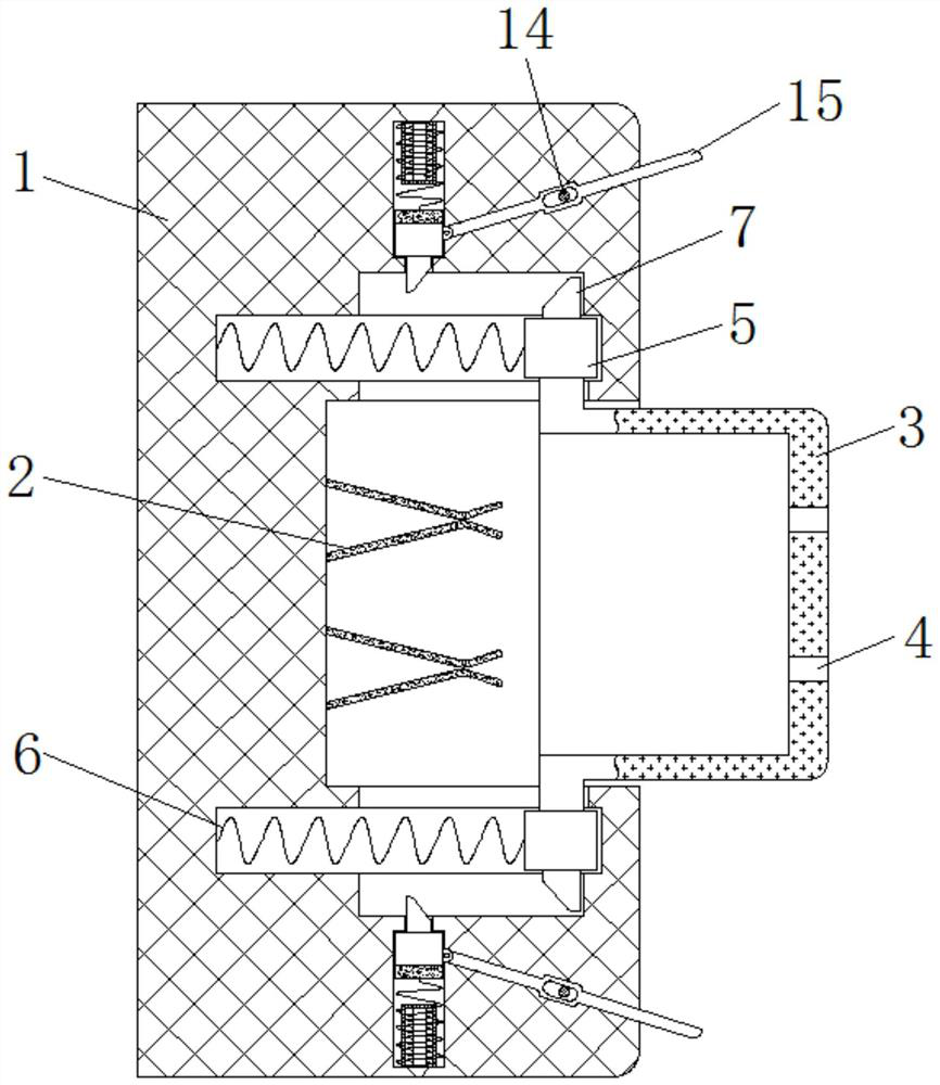
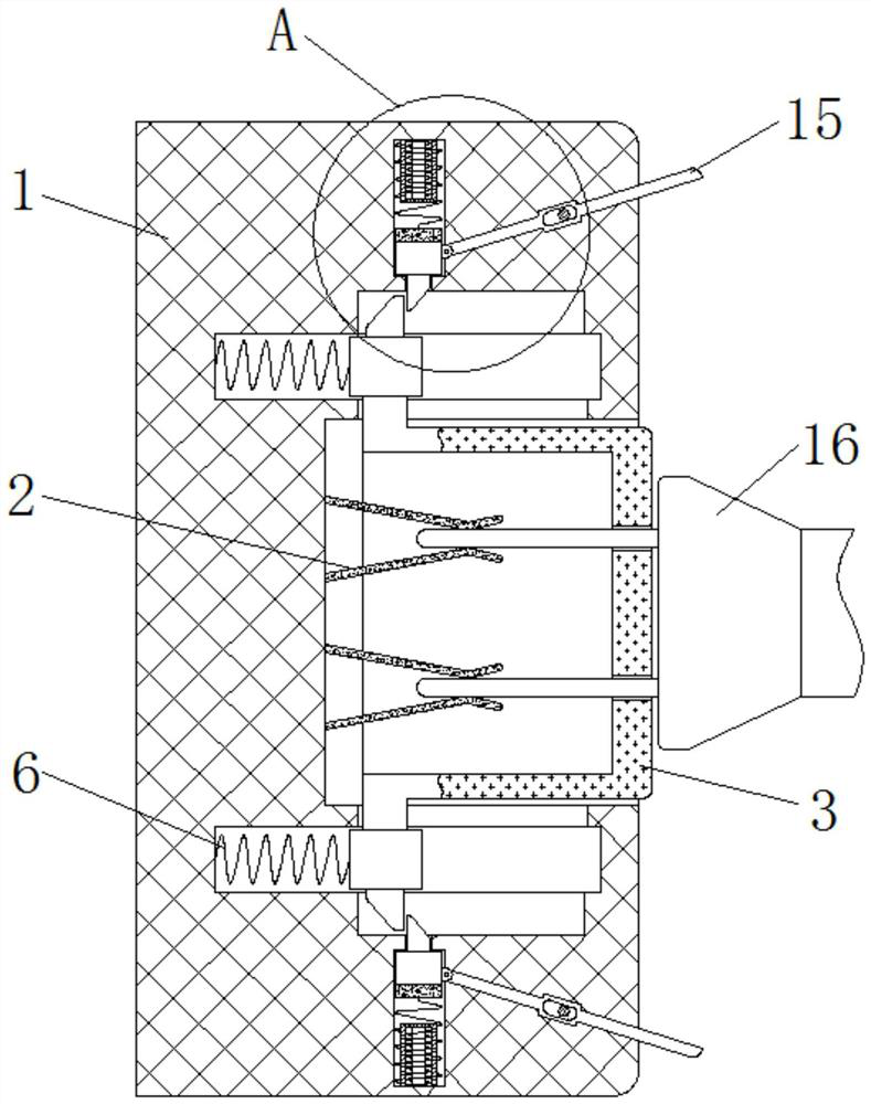
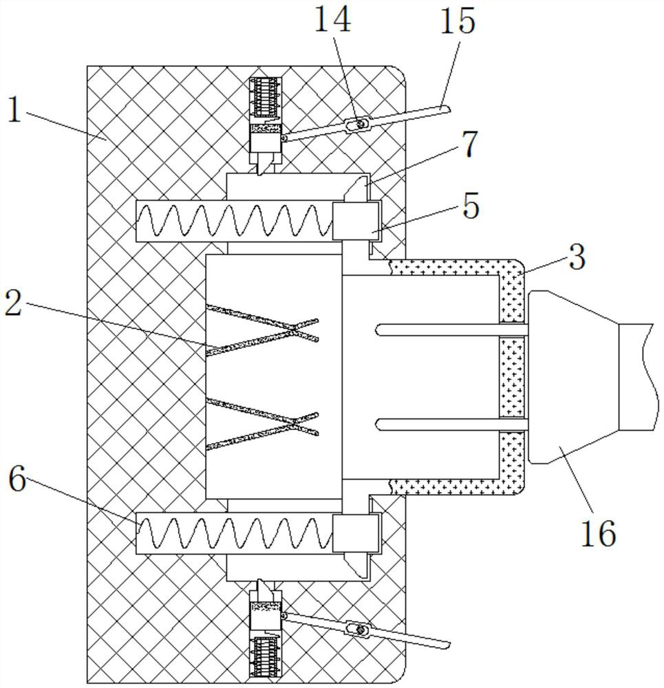
  • Anti-electric-shock wall type socket based on electromagnetic transformation

Examples


Embodiment Construction

[0022] The following will clearly and completely describe the technical solutions in the embodiments of the present invention with reference to the accompanying drawings in the embodiments of the present invention. Obviously, the described embodiments are only some, not all, embodiments of the present invention. Based on the embodiments of the present invention, all other embodiments obtained by persons of ordinary skill in the art without making creative efforts belong to the protection scope of the present invention.

[0023] The embodiment of the anti-shock wall socket based on electromagnetic conversion is as follows:

[0024] see Figure 1-4 , an anti-shock wall socket based on electromagnetic transformation, including a housing 1, an electric contact piece 2, a rectangular cover 3, a socket 4, a slider 5, a first spring 6, a first limiting block 7, a lifting block 8, The second limiting block 9, the second spring 10, the cylinder 11, the iron core 12, the coil 13, the c...


PUM


Abstract

The invention provides an anti-electric-shock wall type socket based on electromagnetic transformation, and relates to the technical field of electrical equipment. The anti-electric-shock wall type socket based on electromagnetic transformation comprises a housing. An electric shock piece is fixedly installed in the housing. The right side of the housing is slidably connected with a rectangular cover. An inserting hole is formed in the right side of the rectangular cover, sliding blocks are fixedly installed at the upper end and the lower end of the left side of the rectangular cover, first springs are fixedly connected to the left ends of the sliding blocks, first limiting blocks are fixedly installed at the ends, away from the center of the rectangular cover, of the sliding blocks, and lifting blocks are slidably connected to the upper side and the lower side of the housing. According to the anti-electric-shock wall type socket based on electromagnetic transformation, the phenomenonthat the plug still has a power connection sheet exposed outside after electric conduction is avoided, so that an electric shock accident does not occur when the plug is plugged in and pulled out, automatic power-off of an electric appliance is realized when a circuit is overloaded, and damage of overload voltage to the electric appliance and the socket is avoided.

Description

technical field [0001] The invention relates to the technical field of electrical equipment, in particular to an electromagnetic transformation-based anti-shock wall socket. Background technique [0002] Socket refers to the insertable seat of one or more circuit connections, can insert various wiring by it, is convenient to connect with other circuit. There are many electrical accessories, which are closely related to people's lives, and in buildings in modern cities, wall power sockets are generally installed. [0003] The traditional wall power outlets are all fixedly installed on the wall. In the process of plugging, the power strip of the plug is directly inserted into the jack, but in the process of plugging, when the power strip is not completely When plugged into the socket, the contact plate is already electrically connected to the contact plate, so that part of the contact plate is still exposed after conducting electricity, making it easier to generate electric s...

Claims


Application Information

Patent Timeline
Patent Type & Authority Applications(China)
IPC IPC(8): H01R13/10H01R13/502H01R13/629H01R13/703H01R13/74
CPCH01R13/74H01R13/629H01R13/7031H01R13/502H01R13/10
Inventor 项新华
Owner 项新华
Learn More