Overhead line system additional line erection traction device

A traction device and catenary technology, applied in the direction of overhead lines, etc., can solve the problems of many construction workers, high risk factor, high labor intensity, etc., and achieve the goal of improving work efficiency, maintaining stable and strong traction force, increasing stability and safety Effect

Inactive Publication Date: 2020-10-02
中铁建电气化局集团第三工程有限公司
View PDF7 Cites 0 Cited by
  • Summary
  • Abstract
  • Description
  • Claims
  • Application Information

AI Technical Summary

Problems solved by technology

[0004] The purpose of this invention is to provide a catenary additional line erection traction device to solve the problems of traditional construction methods requiring many construction workers, low efficiency, high labor intensity and high risk factor

Method used


Image

  • Overhead line system additional line erection traction device
  • Overhead line system additional line erection traction device
  • Overhead line system additional line erection traction device

Examples


Embodiment Construction

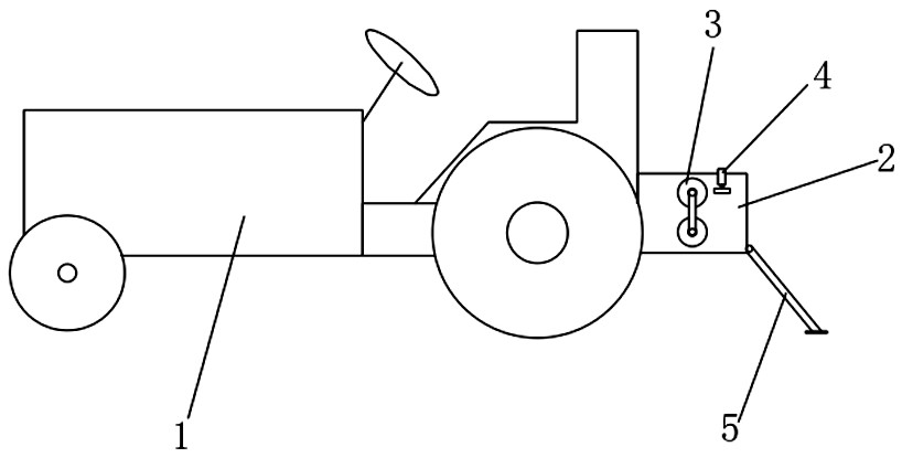
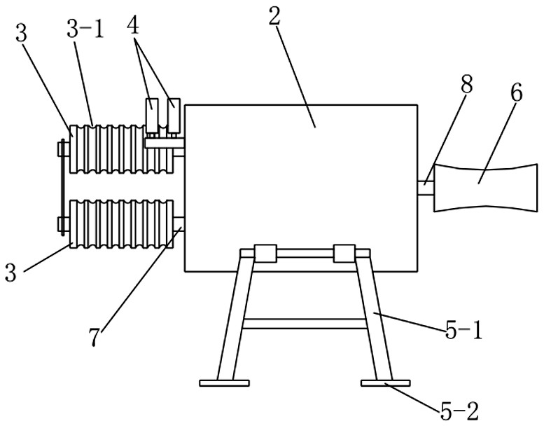
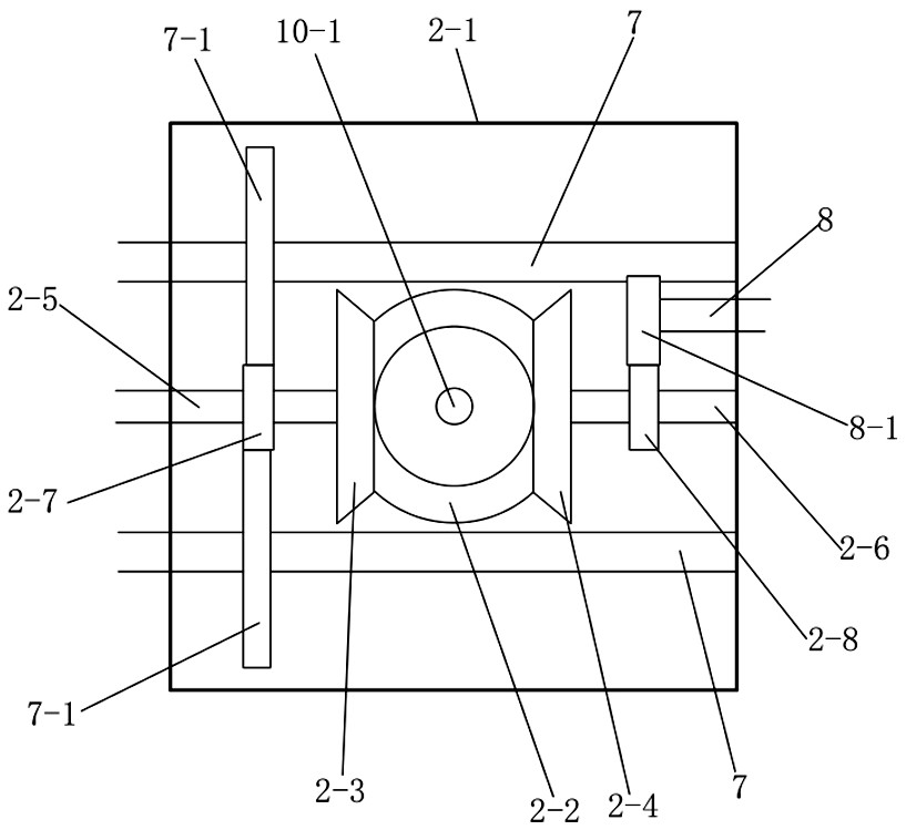
[0018] Such as figure 1 , figure 2 As shown, the present invention includes a tractor 1, a gearbox 2 is arranged at the rear end of the tractor 1, the rear output shaft of the tractor 1 is connected with the power input shaft 9 of the gearbox 2, and a first An output shaft 7, a traction winch 3 is arranged on the first output shaft 7, a second output shaft 8 is stretched out on the other side of the gearbox 2, and a wire winder 6 is arranged on the second output shaft 8, in the transmission Case 2 rear end is provided with anti-reversing support 5.

[0019] Among them, the tractor 1 is a small steering wheel tractor 1 for agricultural use. The small tractor 1 can provide sufficient power, and the driver can easily complete the transfer when the site is changed. The tractor 1 itself has a certain weight and can be more stable during the traction process. .

[0020] There are two traction winches 3, two traction winches 3 are arranged side by side up and down, each traction ...


PUM


Abstract

The invention relates to an overhead line system additional line erecting traction device which structurally comprises a tractor body, a gearbox is arranged at the rear end of the tractor; a rear output shaft of the tractor is connected with a power input shaft of the gearbox; a first output shaft extends out of one side of the gearbox, a traction winch is arranged on the first output shaft, a second output shaft extends out of the other side of the gearbox, a winder is arranged on the second output shaft, and an anti-reversing support is arranged at the rear end of the gearbox. The overhead line system additional line erecting traction device is simple in structure, easy to modify, capable of providing continuous, stable and strong traction force, capable of saving manpower and improvingworking efficiency, safe, reliable and suitable for erecting construction of contact network additional lines of various railways.

Description

technical field [0001] The invention relates to a cable traction device, in particular to a catenary additional line erection traction device. Background technique [0002] The catenary additional lines include power supply lines, reinforcement lines, return lines and overhead ground wires, etc., which are generally framed with the catenary on the same pillar or suspended separately along the railway direction. [0003] The current traditional construction method for erecting the additional conductors of the catenary is to pull the additional wires on the shoulders and spread them out. One person uses a large rope to pull the additional wires to the pole, and then the person on the pole hangs the additional wires on the shoulder frame. This method is simple to operate, but requires A large number of construction workers have high labor intensity, low work efficiency and high risk factor. The traditional construction method is no longer suitable for the erection of additiona...

Claims


Application Information

Patent Timeline
Patent Type & Authority Applications(China)
IPC IPC(8): B60M1/28
CPCB60M1/28
Inventor 王小松马浩尚美金贾树鹏陶志刘凯强安建亮
Owner 中铁建电气化局集团第三工程有限公司
Why Eureka
Try Eureka