


Quick Research
Generate reliable direction feasibility study reports for your R&D in just a few steps.

Technical Q&A
Discover and master advanced knowledge NOW. Basics, ideas, possibilities, all at once.

Find Solutions
As an expert in R&D theories, this can generate solutions to your technical problems instantly.

Evaluate Feasibility
Analyze your overall solution with one click, know your potential R&D risks in advance.

Monitor Landscape
Get weekly tech updates, stay abreast of the latest tech innovations and key insights.
High-pressure hand-operating mechanism
A manual mechanism and high-voltage technology, applied in the direction of contact operating parts, air switch components, etc., can solve the problems of laborious closing structure and lack of buffer structure, etc., and achieve the effect of preventing reverse displacement and improving independence
- Summary
- Abstract
- Description
- Claims
- Application Information
AI Technical Summary
Problems solved by technology
Method used
Image

Examples
Embodiment 1
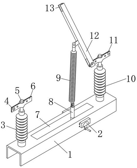
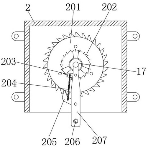
[0037] Example 1, as Figure 1-3 As shown, when the device is opening the gate, at this time, the manual push rod 206 is pushed to drive the connecting rod 207 to rotate, and the connecting rod 207 drives the inner pawl 203 and the outer pawl 205 provided on the outside thereof to jointly push the ratchet 201 to rotate. , the rotation of the ratchet wheel 201 drives the rotation shaft 17 to rotate, and then the rotation of the rotation shaft 17 drives the hinge block 16 on the outer side to rotate, and the rotation of the hinge block 16 pulls the buffer piston 15 for displacement and pushes the hinge column 8 to move upward. The hinge block 16 is supported by the buffer piston 15. When the connecting rod 207 rotates to a position where it is inconvenient to continue to rotate manually at the top, at this time, the manual push rod 206 is reversely rotated to drive the connecting rod 207 to reset. At this time, the inner pawl 203 The one-way meshing state with the inner ratchet ...
Embodiment 2
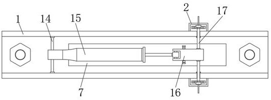
[0038] Example 2, as Figure 4-6 As shown in the figure, the piston rod 22 on the side of the buffer piston 15 is driven by the hinge block 16 to displace so as to generate a squeezing or stretching force on the buffer piston 15, and then the control valve 21 is driven by the piston rod 22 to displace inside the buffer piston 15. The inside of the buffer piston 15 is filled with hydraulic oil, and one end of the buffer piston 15 is provided with a high-pressure nitrogen gas tank 19, so that the inside of the buffer piston 15 is in a high pressure state, and when the control valve 21 is displaced, the hydraulic oil on both sides is The pressure is inconsistent, thereby forcing the hydraulic oil to enter the interior of the installation cavity 27 through the oil inlet passage 28 and push the piston 30 to displace, and at the same time, the compression spring B29 generates a rebound force, so that the high pressure hydraulic oil on one side passes through the oil inlet passage 28 ...
Embodiment 3
[0039] Example 3, as Figure 1-6 As shown in the figure, when closing is required, the manual push rod 206 on the other side of the casting base 1 is rotated to drive the connecting rod 207 to push the ratchet wheel 201 to rotate in the reverse direction, thereby driving the rotating shaft 17 to displace in the reverse direction, and to drive the hinged joint through the rotating shaft 17 The block 16 is reversely rotated to reset, thereby further driving each component to reset, thereby realizing the function of closing.
[0040] Working principle: When the device is in use, the manual mechanism assembly 2 with two sets of reverse structures is provided to achieve independent control of the opening and closing of the high-pressure structure, and the one-way rotation structure inside the manual mechanism assembly 2 and the buffer piston 15 The internal pressure change control cooperates with each other, so as to realize the displacement and support functions of the hinge block...
PUM
 Abstract
Description
Claims
Application Information
 - R&D Engineer
- R&D Manager
- IP Professional
- Industry Leading Data Capabilities
- Powerful AI technology
- Patent DNA Extraction
Browse by: Latest US Patents, China's latest patents, Technical Efficacy Thesaurus, Application Domain, Technology Topic, Popular Technical Reports.
© 2024 PatSnap. All rights reserved.Legal|Privacy policy|Modern Slavery Act Transparency Statement|Sitemap|About US| Contact US: help@patsnap.com