
Water bath type emulsifying machine for cosmetic production and emulsifying method

A technology of water bath and emulsifier, applied in chemical instruments and methods, mixing methods, mixers, etc., can solve the problems of falling raw materials, insufficient emulsification, poor emulsification effect, etc., and achieve the effect of precise feeding and convenient feeding.

Inactive Publication Date: 2020-10-02
朱苗苗
View PDF5 Cites 1 Cited by
  • Summary
  • Abstract
  • Description
  • Claims
  • Application Information

AI Technical Summary

Problems solved by technology

[0007] Most of the existing emulsification devices use exposed design or electric heating: the emulsification temperature of the former is near room temperature, which cannot meet some products with special temperature requirements; the heating area of ​​the latter is concentrated, which will lead to uneven heating of raw materials. The quality of the emulsified product cannot meet the requirements
[0008] Therefore, some emulsification devices adopt a double-layer design, and the temperature is controlled by a water bath. Due to the double-layer design, the temperature of the outer layer and the emulsification of the inner layer need to pass through the outer layer to feed the inner layer. The positioning is inconvenient, and the raw materials often fall. into the outer layer; and as mentioned above, the design of the mixing components of this type of device is unreasonable, and the position of the emulsification stirring area is fixed, resulting in poor emulsification effect and insufficient emulsification degree

Method used


Image

  • Water bath type emulsifying machine for cosmetic production and emulsifying method
  • Water bath type emulsifying machine for cosmetic production and emulsifying method
  • Water bath type emulsifying machine for cosmetic production and emulsifying method

Examples


Embodiment 1

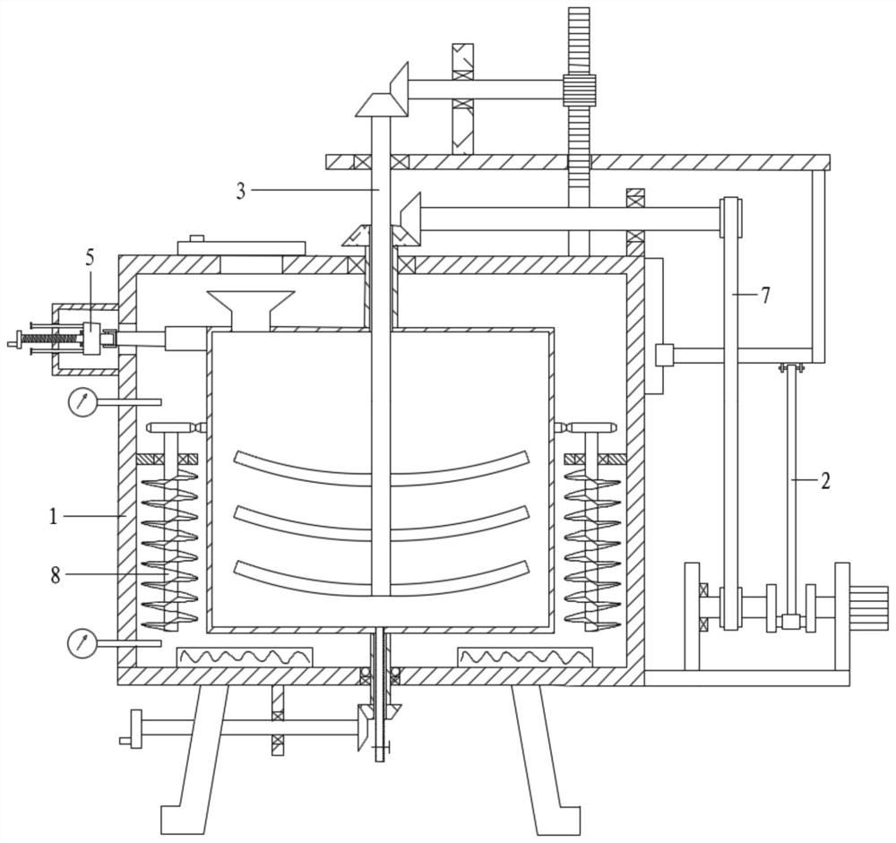
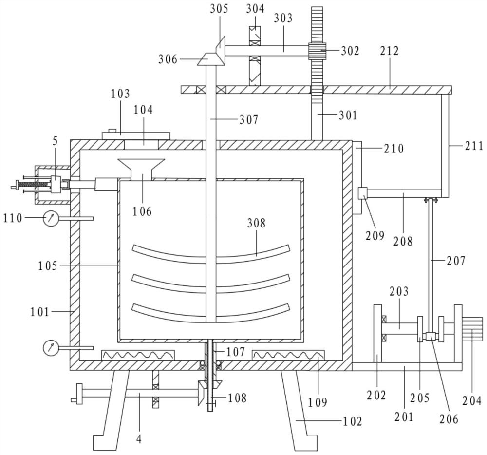
[0059] Referring to the accompanying drawings, a water-bath type emulsifier for cosmetics production includes a tank assembly 1, a lifting assembly 2, an emulsifying assembly 3, a manual adjustment assembly 4, and a positioning assembly 5;

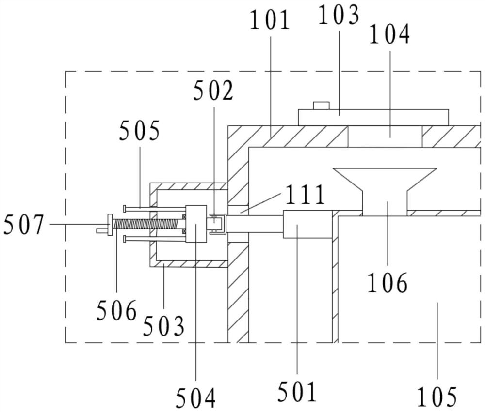
[0060] The tank assembly 1 includes No. 1 tank 101, legs 102, No. 2 tank 105, No. 1 hollow shaft 107, discharge pipe 108, heater 109, thermometer 110 and positioning hole 111; No. 2 tank 105 is arranged on No. 1 tank 101, and set coaxially with No. 1 tank 101; No. 1 tank 101 is equipped with a thermometer 110 at intervals up and down; No. 1 tank 101 is equipped with a heater 109 at the inner bottom; 101 is also connected with water inlet and outlet pipes (not shown), and is equipped with valves for charging or discharging the medium; No. 1 hollow shaft 107 is coaxially connected to the bottom of No. No. tank 101 bottom (the connection is also provided with a sealing ring to avoid water leakage); the bottom of No. 1 hollow shaft 107 protrud...

Embodiment 2

[0062] Referring to the accompanying drawings, a water-bath type emulsifier for cosmetics production includes a tank assembly 1, a lifting assembly 2, an emulsifying assembly 3, a manual adjustment assembly 4, and a positioning assembly 5;

[0063] The tank assembly 1 includes No. 1 tank 101, legs 102, No. 2 tank 105, No. 1 hollow shaft 107, discharge pipe 108, heater 109, thermometer 110 and positioning hole 111; No. 2 tank 105 is arranged on No. 1 tank 101, and set coaxially with No. 1 tank 101; No. 1 tank 101 is equipped with a thermometer 110 at intervals up and down; No. 1 tank 101 is equipped with a heater 109 at the inner bottom; 101 is also connected with water inlet and outlet pipes (not shown), and is equipped with valves for charging or discharging the medium; No. 1 hollow shaft 107 is coaxially connected to the bottom of No. No. tank 101 bottom, (the connection is also provided with a sealing ring, to avoid water leakage); No. 1 hollow shaft 107 bottom extends out ...

Embodiment 3

[0082] On the basis of embodiment 2,

[0083] Also includes rotating assembly 7; rotating assembly 7 includes No. 1 transmission wheel 701, transmission belt 702, No. 2 transmission wheel 703, No. 5 rotating shaft 704, No. 5 support plate 705, No. 5 bevel gear 706, No. 6 bevel gear 707 and No. 2 hollow shaft 708;

[0084] No. 1 transmission wheel 701 is installed on No. 1 shaft 203; No. 5 support plate 705 is fixedly connected to the right end of No. 1 tank 101 top, No. 5 shaft 704 runs through and rotatably connects No. 5 support plate 705; No. 2 shaft 704 is installed on the right end Transmission wheel 703, No. 2 transmission wheel 703 and No. 1 transmission wheel 701 are connected by transmission belt 702; No. 5 bevel gear 706 is fixedly connected to the left end of No. 5 rotating shaft 704; No. 2 hollow shaft 708 is coaxially connected to the top of No. 2 tank 105, No. 2 hollow shaft 708 passes through and connects the top of No. 1 tank 101 through bearing rotation; No. ...


PUM


Abstract

The invention relates to the technical field of cosmetic production and emulsification, in particular to a water bath type emulsifying machine for cosmetic production and an emulsifying method. The plug is moved leftwards through the positioning assembly, so that the positioning hole is opened; the second tank is driven to rotate through the manual adjustment assembly; when the rolling wheel movesto the positioning hole, the spring rod automatically extends to penetrate through the positioning hole to limit the second tank, and at the moment, the feeding hopper is aligned with the feeding port, so that accurate feeding is facilitated; and the servo motor is started, so that the lifting assembly drives the lifting plate to ascend and descendin a reciprocating manner, the lifting plate synchronously drives the emulsifying assembly to move up and down, and the emulsifying assembly rotates to fully stir and emulsify raw materials in the second tank.

Description

technical field [0001] The invention relates to the technical field of cosmetic production emulsification, in particular to a water-bath emulsification machine and an emulsification method for cosmetic production. Background technique [0002] Emulsification is the effect of one liquid uniformly dispersed in another immiscible liquid in the form of tiny droplets. Emulsification is a liquid-liquid interface phenomenon. Two immiscible liquids, such as oil and water, are divided into two layers in a container. The oil with low density is in the upper layer, and the water with high density is in the lower layer. If appropriate surfactant is added and the oil is dispersed in water under strong stirring, an emulsion is formed. This process is called emulsification. [0003] Emulsification is one of the key processes in the production process of cosmetics, which determines the quality of cosmetic products to a certain extent. [0004] Emulsification requires the use of an emulsif...

Claims


Application Information

Patent Timeline
IPC IPC(8): B01F11/00B01F15/00B01F15/02B01F15/06B01F3/08
CPCB01F23/41B01F31/40B01F35/00B01F35/2215B01F35/716B01F35/90B01F2035/99
Inventor 朱苗苗
Owner 朱苗苗
Learn More