Wide-purpose block-mounted dust removal filter bag

A filter bag and application technology, which is applied in the field of wide-purpose block-mounted dust filter bags, can solve the problems of low installation efficiency, winding, complicated installation of dust filter bags, etc., and achieve the effect of avoiding winding and good effect

Active Publication Date: 2020-10-02
安徽世倾环保科技有限公司
View PDF31 Cites 2 Cited by
  • Summary
  • Abstract
  • Description
  • Claims
  • Application Information

AI Technical Summary

Problems solved by technology

[0004] However, when the existing dust filter bags are used, the installation of the dust filter bags is complicated and the installation efficiency is low. In addition, the dust filter bags are also prone to entanglement during use, which makes the use effect of the dust filter bags not good.

Method used


Image

  • Wide-purpose block-mounted dust removal filter bag
  • Wide-purpose block-mounted dust removal filter bag
  • Wide-purpose block-mounted dust removal filter bag

Examples


Embodiment 1

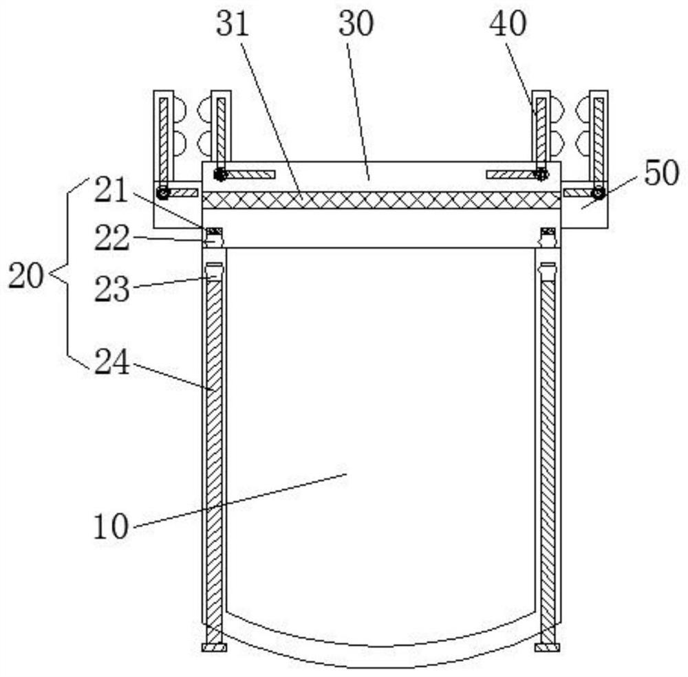
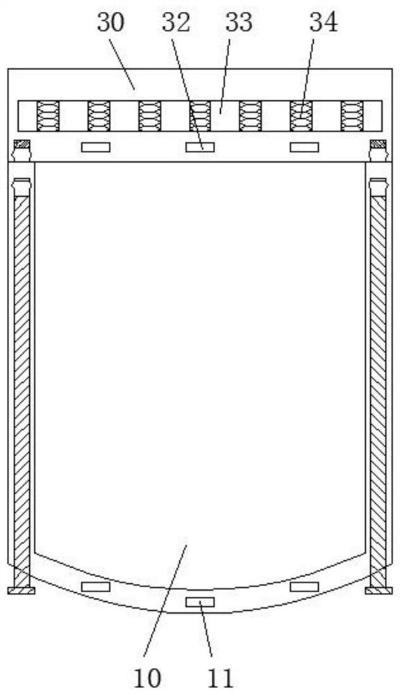
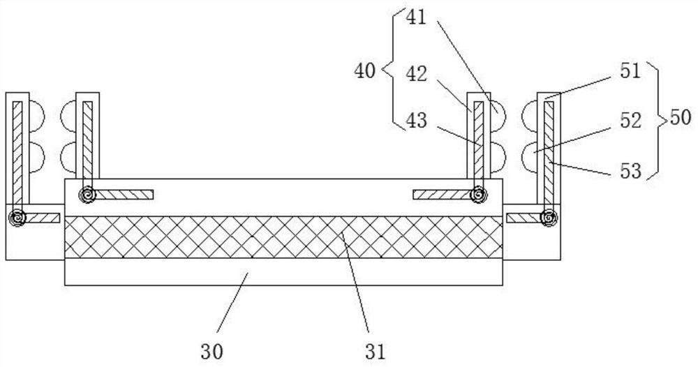
[0024] Such as Figure 1-4 As shown, a wide-purpose block-mounted dust filter bag includes a dust filter bag body 10, a positioning mechanism 20, a connecting ring 30, a first clip 40, and a second clip 50. The dust filter bag body The top of the top of 10 is provided with a connecting ring 30, and a positioning mechanism 20 is provided between the dust filter bag body 10 and the connecting ring 30, and the top of the connecting ring 30 is symmetrically provided with a first clamping piece near the edge. 40 and the second clip 50, the inside of the connection ring 30 is provided with a placement groove 33, and the placement groove 33 is provided with a buffer spring 34, and the side wall of the connection ring 30 is opposite to the placement groove 33 An elastic sealing strip 31 is provided at the position.

[0025] A connection ring 30 is provided on the dust filter bag body 10, and a first clamping member 40 and a second clamping member 50 are arranged symmetrically on the ...

Embodiment 2

[0034] Such as Figure 2-6As shown, a wide-purpose block-mounted dust filter bag includes a dust filter bag body 10, a positioning mechanism 20, a connecting ring 30, a first clip 40, and a second clip 50. The dust filter bag body 10 is provided with a connecting ring 30 on the top, and a positioning mechanism 20 is provided between the dust filter bag body 10 and the connecting ring 30. The top of the dust filter bag body 10 is symmetrically provided with a first clamping joint near the edge. 40 and the second clamping member 50, the inside of the connecting ring 30 is provided with a placement groove 33, and the buffer spring 34 is arranged in the placement groove 33, and the side wall of the connecting ring 30 is relatively opposite to the placement groove An elastic sealing band 31 is provided at the position 33 .

[0035] The first clamping member 40 includes a first protrusion 41, a fixed rod 42 and a first return spring 43, the fixed rod 42 is arranged near the edge of...


PUM

PropertyMeasurementUnit
dust removal efficiencyaaaaaaaaaa

Abstract

The invention provides a wide-purpose block-mounted dust removal filter bag. The dust removal filter bag comprises a dust removal filter bag body, a positioning mechanism, a connecting circular ring,a first clamping piece and a second clamping piece, wherein the connecting circular ring is arranged at the top of the dust removal filter bag body; the positioning mechanism is arranged between the dust removal filter bag body and the connecting circular ring; the first clamping piece and the second clamping piece are symmetrically arranged at the position, close to the edge, of the top of the connecting circular ring; a containing groove is formed in the connecting circular ring, and a buffer spring is arranged in the containing groove. The block-mounted dust removal filter bag is advantageous in that the positioning mechanism is arranged between the dust removal filter bag body and the connecting circular ring so that the position between the dust removal filter bag body and the connecting circular ring can be limited through the positioning mechanism, and the shape of the dust removal filter bag body can be limited, the winding phenomenon of the dust removal filter bag body in theuse process is avoided, and the filtering and dust removal effects of the dust removal filter bag body are better.

Description

technical field [0001] The invention relates to the technical field of dust removal equipment, in particular to a wide-purpose block-mounted dust removal filter bag. Background technique [0002] Dust removal filter material is a kind of high-efficiency dust removal filter material. The dust removal filter bag is made of polyester staple fiber, pps fiber, pp polypropylene, aramid fiber, aramid fiber, etc., and its service life is generally 2-4 years. Excellent air permeability, high dust collection rate, easy to clean dust, dust removal efficiency can reach 98.99%. Has good removal of PM2.5. [0003] The filter bag is the heart of the bag filter during operation. Usually, the cylindrical pulse type filter bag is hung vertically in the dust collector. Part of the large particle dust is separated by the inertial force and falls directly into the ash hopper. The dusty gas enters the filter bag filter area of ​​the box, and most of the dust is captured on the outer surface of...

Claims


Application Information

Patent Timeline
Patent Type & Authority Applications(China)
IPC IPC(8): B01D46/02B01D46/00
CPCB01D46/02B01D46/0005B01D46/88
Inventor 房利生许瑞生钱丰梁运动吴秀秀
Owner 安徽世倾环保科技有限公司
Why Eureka
Try Eureka