
Heavy-load parallel type state switching device

A state transition, parallel technology, applied in rocket launchers, offensive equipment, weapon types, etc., can solve problems such as large size and inability to meet heavy load requirements

Active Publication Date: 2020-09-29
BEIJING INST OF SPACE LAUNCH TECH
View PDF4 Cites 2 Cited by
  • Summary
  • Abstract
  • Description
  • Claims
  • Application Information

AI Technical Summary

Problems solved by technology

At present, the structural forms of the state conversion devices of launch platforms of various types of launch vehicles cannot meet the heavy load requirements, and the volume is relatively large

Method used


Image

  • Heavy-load parallel type state switching device
  • Heavy-load parallel type state switching device
  • Heavy-load parallel type state switching device

Examples


Embodiment Construction

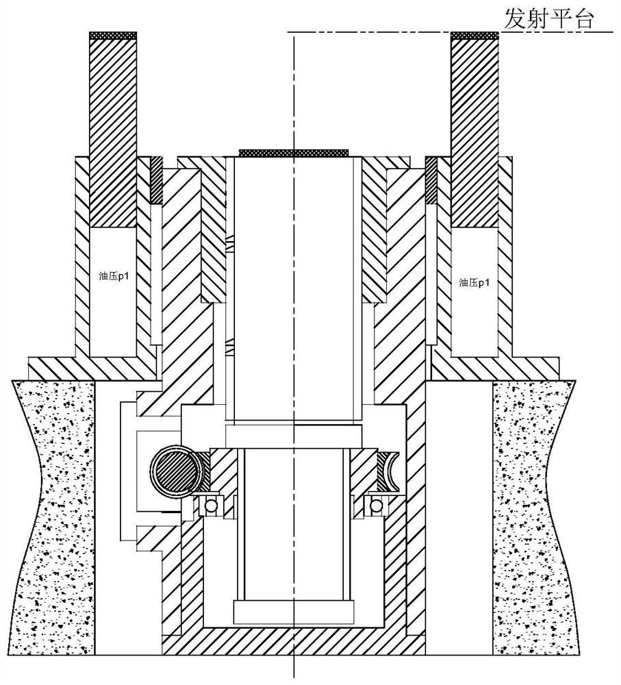
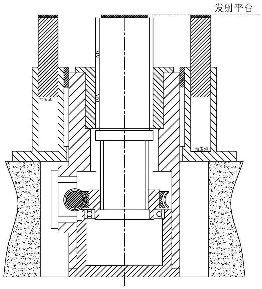
[0019] Such as figure 1 Shown and combined figure 2 , 3 As shown, the heavy-duty parallel state conversion device of the present invention includes an annular oil cylinder 1 in which an annular piston 2 is installed in the cylinder body. The annular piston 2 can slide up and down along the central axis in the cylinder body of the annular oil cylinder 1. A support 5 is provided in the middle of the annular oil cylinder 1, a nut 6 is fixed on the support 5, and a screw 7 is connected to the inner thread of the nut 6, and the screw 7 is rotatably mounted on the support 5. The screw 7 is connected with a driving device, and the driving device drives the screw 7 to rotate. Since the screw 7 and the nut 6 are screw-fitted, and the nut 6 is fixedly connected to the support 5, the screw 7 can move along the central axis of the nut 6 when rotating, that is, extend upward or retract downward.

[0020] The heavy-duty parallel state conversion device of the present invention, wherein the su...


PUM


Abstract

The invention discloses a heavy-load parallel type state switching device. The heavy-load parallel type state switching device comprises an annular oil cylinder. An annular piston is mounted in a cylinder block of the annular oil cylinder. A support is arranged in the middle position of the annular oil cylinder. A nut is fixedly arranged on the support. The nut is internally in threaded connectionwith a screw rod. The screw rod is rotatably mounted on the support. The screw rod is connected with a driving device. The driving device drives the screw rod to rotate. The invention aims to providethe heavy-load parallel type state switching device which is compact in structure and capable of meeting the requirements for heavy-load bearing.

Description

Technical field [0001] The invention relates to the field of rocket launches, in particular to a state conversion device for a rocket launch platform. Background technique [0002] The heavy-duty parallel state conversion device is used to realize the conversion between the walking state and the launch state of the heavy launch vehicle launching platform. When the movable launching platform is transferred from the technical station to the launching station, the conversion device is raised to lift the launching platform to At a certain height, the walking mechanism is lifted off the ground to complete the transition from the walking state to the launch state; after the rocket is launched, the conversion device is retracted, and the walking mechanism touches the ground to carry it, completing the transition from the launch state to the walking state. At present, the structural form of the launch platform status conversion device of various types of launch vehicles cannot meet the n...

Claims


Application Information

Patent Timeline
IPC IPC(8): F41F3/04
CPCF41F3/04
Inventor 居龙任晓伟黎定仕徐铮张国栋王南吴新跃
Owner BEIJING INST OF SPACE LAUNCH TECH
Learn More