Waste liquid collecting system and method for chemical device

A waste liquid collection and waste liquid technology, applied in pipeline systems, gas/liquid distribution and storage, pipes/pipe joints/pipe fittings, etc., can solve problems such as environmental pollution, achieve the effect of simple and compact structure and improve production stability

Inactive Publication Date: 2020-09-29
CHINA SHENHUA COAL TO LIQUID & CHEM CO LTD +1
View PDF8 Cites 1 Cited by
  • Summary
  • Abstract
  • Description
  • Claims
  • Application Information

AI Technical Summary

Problems solved by technology

[0003] The purpose of the present invention is to provide a chemical plant waste liquid collection system and collection method in order to overcome the environmental pollution caused by unorganized discharge in the prior art. In the waste liquid storage tank, the gas pressure in the buried waste liquid storage tank is monitored in real time, and the waste gas and waste liquid are discharged and treated separately in a timely and effective manner to ensure the effective temporary storage, reuse or delivery of waste liquid. The structure Simple and compact, improve production stability

Method used


Image

  • Waste liquid collecting system and method for chemical device
  • Waste liquid collecting system and method for chemical device
  • Waste liquid collecting system and method for chemical device

Examples


Embodiment Construction

[0028] Specific embodiments of the present invention will be described in detail below in conjunction with the accompanying drawings. It should be understood that the specific embodiments described here are only used to illustrate and explain the present invention, and are not intended to limit the present invention.

[0029] In the present invention, in the case of no contrary description, the used orientation words such as "up, down, left and right" usually refer to the up, down, left and right shown in the accompanying drawings; "inside and outside" Usually refers to the inside and outside relative to the outline of each part itself; "far and near" usually refers to the distance relative to the outline of each part itself.

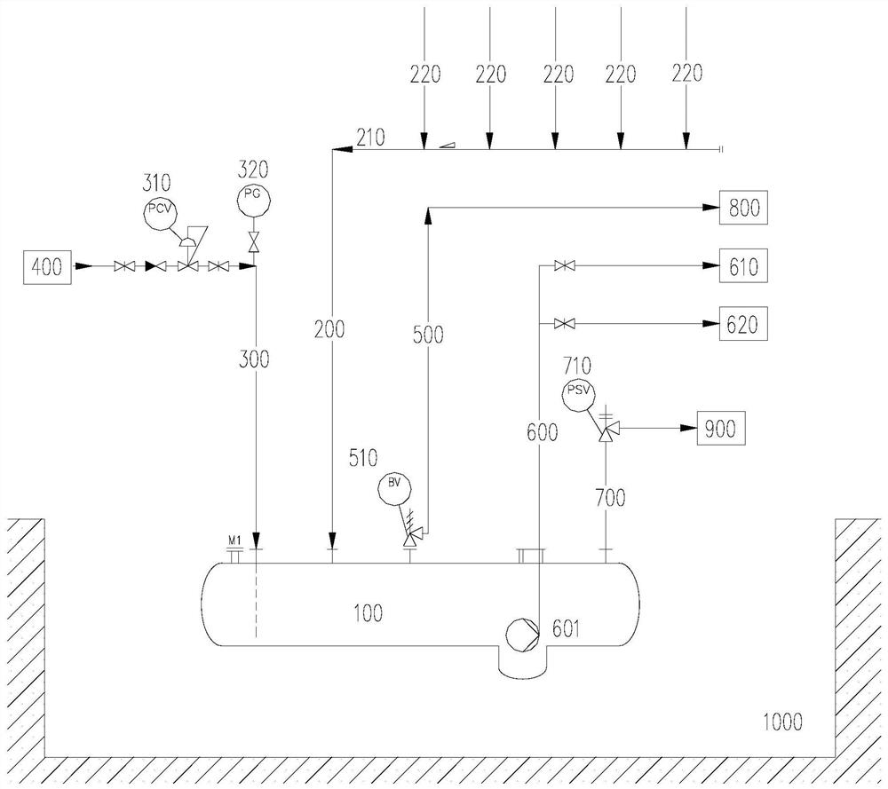
[0030] Such as figure 1 As shown, the present invention provides a chemical plant waste liquid collection system, including a buried waste liquid storage tank 100 arranged in a ground tank 1000 sunk on the ground plane and a waste liquid storage tank 1...


PUM


Abstract

The invention relates to the technical field of environmental protection, and discloses a waste liquid collecting system and method for a chemical device. The waste liquid collecting system for the chemical device comprises an underground waste liquid storage tank (100) arranged in a geosynclines (1000) sinking into the ground plane and a waste liquid inputting pipeline (200) arranged on the underground waste liquid storage tank; an inert gas inputting pipeline (300) is arranged on the underground waste liquid storage tank and connected with an external inert gas source (400), and a first gasexhausting pipeline (500) used for gas exhausting under the normal working condition is arranged on the underground waste liquid storage tank; and a one-way breather valve (510) is arranged on the first gas exhausting pipeline, and a waste liquid discharging pipeline (600) is arranged on the underground waste liquid storage tank. Different waste liquid is intensively collected in the underground waste liquid storage tank, the gas pressure in the underground waste liquid storage tank is monitored in real time, waste gas and the waste liquid are effectively discharged in time and treated, effective temporary storage, reusing or outward conveying treatment of the waste liquid is guaranteed, the structure is simple and compact, and the production stability is improved.

Description

technical field [0001] The invention relates to the technical field of environmental protection, in particular to a waste liquid collection system and a collection method of a chemical plant. Background technique [0002] In order to meet the requirements of environmental protection, the discharge of waste liquid in chemical plants needs to be collected in a closed manner and undergo process recovery or harmless treatment to reduce environmental pollution. However, at present, the discharge of waste liquid in chemical plants has the characteristics of many discharge points, low discharge pressure, and large discharge volume changes. In view of the fact that it is difficult to collect through ordinary vertical airtight pressure vessels, the existing technology has gradually improved the waste liquid collection by adopting the floor tank system. The floor tank system is usually set to in-situ unorganized discharge or ordinary floor tank collection, which can effectively collec...

Claims


Application Information

Patent Timeline
IPC IPC(8): F17D1/02F17D1/08F17D3/01F17D5/00F16L55/07
CPCF16L55/07F17D1/02F17D1/08F17D3/01F17D5/00
Inventor 吴金华崔奇田丹霖张华许朝阳
Owner CHINA SHENHUA COAL TO LIQUID & CHEM CO LTD
Why Eureka
Try Eureka