Electronic shifter and control method thereof

A technology of electronic shifter and control method, which is applied in transmission control, components with teeth, belts/chains/gears, etc., which can solve the problems of easy touch of arms, unreliable positioning, and occupation of the whole vehicle, etc., to achieve The structure is simple and reliable, and the effect of occupying a small space

Active Publication Date: 2021-10-08
浙江科思泰智能科技有限公司
View PDF0 Cites 0 Cited by
  • Summary
  • Abstract
  • Description
  • Claims
  • Application Information

AI Technical Summary

Problems solved by technology

[0003] Among them, the operation of the lever-type shifter is complicated. After starting the car, step on the brake, press the unlock button and drag the handle to the desired gear, which is inconvenient for maintenance and takes up a lot of space in the vehicle. It is located between the driver and the co-driver. The protrusion affects the aesthetic effect, and it is easy to touch it when moving in the car, causing a lot of inconvenience
[0004] Among them, the assembly position of the gear shifter is on the side of the steering wheel, and a long operating part is extended. The wiper originally installed here needs to be moved to the left side of the steering wheel, which increases the complexity of the overall structure of the steering wheel. The part is easy to touch, and it is easy to touch when turning and turning the steering wheel, which takes up a lot of space in the vehicle and the overall layout is not neat
[0005] Among them, the installation position of the knob-type shifter and the button-type shifter is low, and the driver needs to look down when operating, which affects driving safety. Inattention can easily cause gear switching errors, and the driver needs to look down during the process of reverse parking. Only the gear button can be operated, and blind operation and continuous operation cannot be achieved. The self-locking force point of the cam mechanism generates a component force, causing the gear shaft to be subjected to tangential and normal forces at the same time, and the positioning is unreliable. Further improvement is needed.

Method used


Image

  • Electronic shifter and control method thereof
  • Electronic shifter and control method thereof
  • Electronic shifter and control method thereof

Examples


Embodiment Construction

[0059] The present invention discloses an electronic shifter and a control method of the electronic shifter. The specific implementation manners of the present invention will be further described below in combination with preferred embodiments.

[0060] The "locking structure", "locking mechanism", "self-locking structure", and "self-locking mechanism" that may be involved in various embodiments of the present invention are the same concept and will not be distinguished.

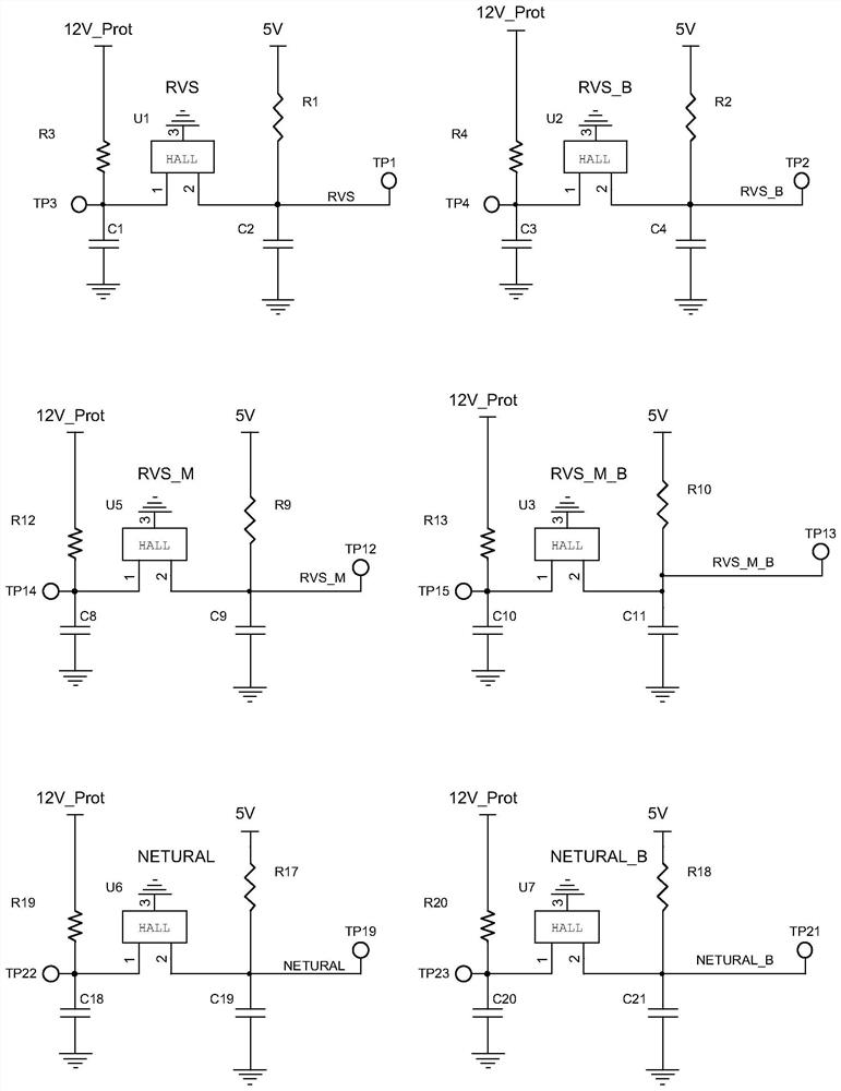
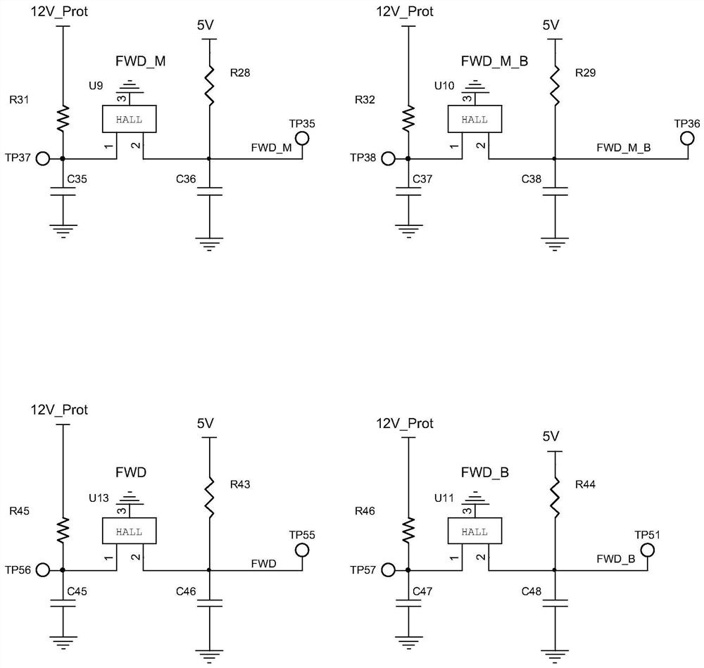
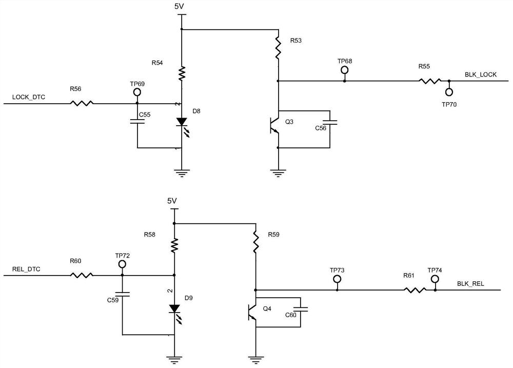
[0061] see attached Figure 1A and Figure 1B , respectively showing a partial circuit structure of the gear sensor of the present invention; figure 2 Shows the circuit structure of the unlocking and locking module of the present invention; image 3 Shows the circuit structure of the main connector of the present invention; Figure 4 Shows the circuit structure of the start switch interface of the present invention; Figure 5A and Figure 5B Partial circuit structures of the power management module of t...


PUM


Abstract

The invention discloses an electronic shifter and a control method thereof. The electronic shifter includes a shift shaft, a locking gear, a motor, a worm, a photoelectric sensor for an unlocked position, a photoelectric sensor for a locked position and a circuit board, wherein: all the components located inside the electronic shifter The motor is started under control by a control circuit located on the circuit board; the worm is in transmission connection with the locking gear, so that the unlocking position photoelectric sensor block rotates synchronously with the locking gear. The electronic shifter and its control method disclosed by the present invention occupy a small space, and integrate the locking cam, gear, and optocoupler block into the locking gear. In the locked state, the force on the gear shaft is only one direction, and the There is no component force in other directions, and the structure is more concise and reliable. The reduction of the overall structure does not make the shifter function missing, and at the same time leaves sufficient space for other parts of the vehicle to be arranged.

Description

technical field [0001] The invention belongs to the technical field of electric appliances for vehicles, and in particular relates to an electronic shifter and a control method for the electronic shifter. Background technique [0002] Vehicle shifters currently on the market are mainly rod-type shifters, gear shifters, knob-type shifters, and button-type shifters. [0003] Among them, the operation of the lever-type shifter is complicated. After starting the car, step on the brake, press the unlock button and drag the handle to the desired gear, which is inconvenient for maintenance and takes up a lot of space in the vehicle. It is located between the driver and the co-driver. The bulge affects the aesthetic effect, and it is very easy to touch it when moving in the car at ordinary times, causing a lot of inconvenience. [0004] Among them, the assembly position of the gear shifter is on the side of the steering wheel, and a long operating part is extended. The wiper origin...

Claims


Application Information

Patent Timeline
Patent Type & Authority Patents(China)
IPC IPC(8): F16H61/02F16H61/32F16H59/12
CPCF16H59/12F16H61/0213F16H61/32F16H2061/2892F16H2061/326
Inventor 张攀袁世冬张永祥
Owner 浙江科思泰智能科技有限公司
Why Eureka
Try Eureka