A heat dissipation structure for a water pump motor driver

A technology of water pump motor and heat dissipation structure, which is applied to the structural parts of electrical equipment, electrical components, cooling/ventilation/heating transformation, etc., which can solve the problems of high energy consumption, reduced service life of drivers, and high operating frequency of electronic components, and achieve effective results Good, improved cooling effect, simple structure, convenient and practical effect

Active Publication Date: 2022-05-03
JIANGSU JIARUN RAINMAKER
View PDF6 Cites 0 Cited by
  • Summary
  • Abstract
  • Description
  • Claims
  • Application Information

AI Technical Summary

Problems solved by technology

But the current servo motor driver has many electronic components. When the motor needs bidirectional rotation or speed regulation, the motor driver needs to be equipped with existing technologies such as control unit and chip and other electronic units to realize the operation. The operating frequency of the electronic components is high and the energy consumption is high. , will generate a lot of heat, and the cooling fins and thermal pads alone cannot meet the heat dissipation requirements of the larger servo motor driver, which will lead to a reduction in the service life of the driver. Therefore, a heat dissipation structure for the water pump motor driver is proposed

Method used


Image

  • A heat dissipation structure for a water pump motor driver
  • A heat dissipation structure for a water pump motor driver
  • A heat dissipation structure for a water pump motor driver

Examples


Embodiment

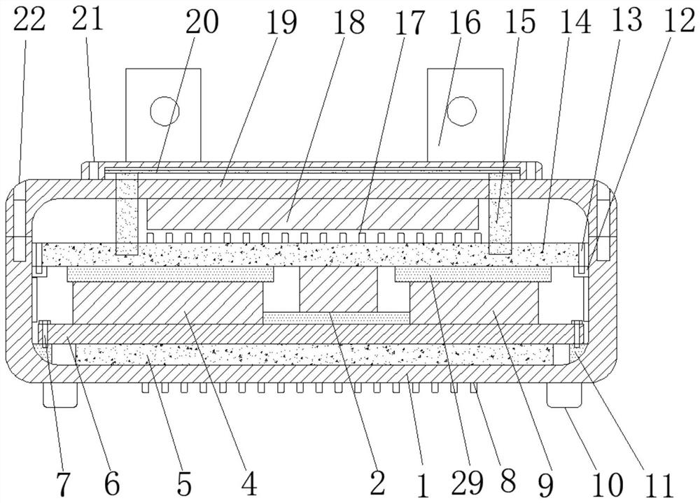
[0019] see Figure 1-4 , the present invention provides a technical solution: a heat dissipation structure for a water pump motor driver, including a first housing 1, four first fixing blocks 11 are symmetrically welded on the inner bottom wall of the first housing 1, four first fixing blocks 11 are welded symmetrically, The upper surface of a fixed block 11 is fixedly connected with the circuit board 6 through the first bolt 7, the upper surface of the circuit board 6 is fixedly connected with the first electronic component 4 and the second electronic component 9, the first electronic component 4 and the second electronic component The upper surface of 9 is bonded with a third thermal pad 29, and the inner wall of the first housing 1 is symmetrically welded with two second fixing blocks 12, and the upper surfaces of the two second fixing blocks 12 are fixed by second bolts 13 A copper heat conduction plate 14 is connected, the lower surface of the copper heat conduction plate...


PUM


Abstract

The invention discloses a heat dissipation structure for a water pump motor driver, which comprises a first casing, four first fixing blocks are symmetrically welded on the inner bottom wall of the first casing, and four first fixing blocks are welded symmetrically. The upper surface is fixedly connected with a circuit board through first bolts, the upper surface of the circuit board is fixedly connected with a first electronic component and a second electronic component, and the upper surfaces of the first electronic component and the second electronic component are bonded with The third heat-conducting rubber pad solves the situation that the servo motor driver has many components and high operating frequency and high energy consumption will generate a lot of heat, which meets the heat dissipation requirements of the motor driver and ensures the normal service life of the driver. It has an air inlet , can work with the fan circulation to dissipate heat from the internal components. The third plate is more convenient to disassemble, which provides convenience for users to clean the internal dust. After cleaning the dust, the heat dissipation effect will be better. The structure is simple, convenient and practical, and the heat dissipation effect is effective. higher lift.

Description

technical field [0001] The invention relates to the technical field of motor equipment, in particular to a heat dissipation structure for a water pump motor driver. Background technique [0002] The motor driver is the controller used to control the motor, which is usually part of the motor system; when the AC motor is used, it usually needs to be given a low voltage and high current to complete the start, and after starting to rotate, it returns to the normal rated current and rated voltage, while Variation of the motor current is usually accomplished using a motor driver. During the working process of the motor driver, its power chip and the resistance loss and switching loss will continue to generate a large amount of heat. Structural design is one of the key technologies that affect the performance of motor drives. [0003] Chinese invention CN101500398A discloses a heat dissipation structure of a motor driver, in which the two ends of the upper and lower casings of th...

Claims


Application Information

Patent Timeline
Patent Type & Authority Patents(China)
IPC IPC(8): H05K7/20H05K5/02
CPCH05K7/20136H05K7/20145H05K7/2039H05K7/20418H05K7/20445H05K7/20454H05K7/205H05K5/0217H05K5/0213
Inventor 李伟
Owner JIANGSU JIARUN RAINMAKER
Why Eureka
Try Eureka