On-duty flame stabilizing cavity of trapped vortex combustion chamber and oil-gas matching device

A technology for matching devices and combustion chambers, applied in combustion chambers, continuous combustion chambers, combustion methods, etc., can solve problems such as unsatisfactory oil and gas mixing, and achieve the effect of improving lean oil flameout limit, increasing effective combustion time, and saving time.

Active Publication Date: 2020-09-25
CHINA AERODYNAMICS RES & DEV CENT
View PDF12 Cites 7 Cited by
  • Summary
  • Abstract
  • Description
  • Claims
  • Application Information

AI Technical Summary

Problems solved by technology

[0004] The present invention intends to provide an on-duty flame-stabilizing cavity and an oil-gas matching device for a vortex combustor to solve the problem of unsatisfactory oil-gas mixing in the existing vortex combustor

Method used


Image

  • On-duty flame stabilizing cavity of trapped vortex combustion chamber and oil-gas matching device

Examples


Embodiment Construction

[0017] The present invention will be described in further detail below by means of specific embodiments:

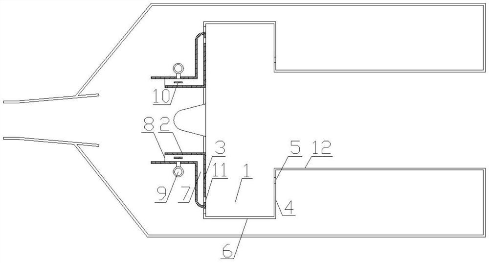
[0018] The reference signs in the drawings of the description include: cavity 1, deflector 2, cavity front wall 3, cavity rear wall 4, second air inlet 5, cavity bottom wall 6, premixing cavity 7, the first An air inlet 8, an oil supply pipe 9, an oil splash plate 10, an oil injection hole 11, and a combustion chamber 12.

[0019] The embodiment is basically as attached figure 1 Shown: a vortex combustor 12 on-duty flame-stabilizing concave cavity 1 and an oil-gas matching device, including a concave cavity 1 with a top opening and a deflector 2 located on the front wall of the concave cavity 1, the rear wall of the concave cavity 1 and the combustion chamber 12. The side wall is made by one-piece molding process. The length of the front wall of the cavity 1 is greater than the length of the rear wall of the cavity 1. Both the front wall and the rear wall of the cavity 1...


PUM


Abstract

The invention discloses an on-duty flame stabilizing cavity of a trapped vortex combustion chamber and an oil-gas matching device, and particularly relates to the technical field of aviation gas turbine combustion. The on-duty flame stabilizing cavity of the trapped vortex combustion chamber and the oil-gas matching device comprise a cavity and a flow guide plate located on the front wall surfaceof the cavity, wherein a premixing cavity is formed between the front wall surface of the cavity and the flow guide plate; a first air inlet is formed in the premixing cavity; an oil supply pipe and oil splashing plates arranged outside the oil supply pipe at intervals are arranged on the premixing cavity; an oil spraying hole communicating with the cavity is further formed in the premixing cavity; and the oil spraying hole is far away from the bottom wall of the cavity. By the adoption of the technical scheme, the problem that oil-gas mixing of an existing trapped vortex combustion chamber isnot ideal is solved, and the stability of flames under the low oil-gas ratio and the combustion efficiency of on-duty classes under the high oil-gas ratio can be improved.

Description

technical field [0001] The invention relates to the technical field of aviation gas turbine combustion, in particular to a duty-level flame-stabilizing cavity and an oil-gas matching device for a vortex combustion chamber. Background technique [0002] The trapped vortex combustor (Trapped Vortex Combustor, TVC) is an innovative combustion organization scheme that utilizes the trapped vortex cavity in the combustion chamber to achieve flame stability. It has stable performance in a wide working range, strong ground / air ignition energy and high combustion efficiency. High, short length, simple structure and so on. The trapped vortex combustor is mainly composed of two parts: a trapped vortex class combustion zone for stabilizing the flame and a main combustion zone for power supply. The vortex combustion organization technology adopts the design idea of ​​radial classification and partition: among them, the double-sided concave cavity is its main structural feature, which as...

Claims


Application Information

Patent Timeline
Patent Type & Authority Applications(China)
IPC IPC(8): F23R3/30F23R3/38
CPCF23R3/30F23R3/38
Inventor 龚诚邱名赫颜赵姝帆蒋筑宇
Owner CHINA AERODYNAMICS RES & DEV CENT
Why Eureka
Try Eureka