
a corn seeder

A technology of corn seeder and conveying mechanism, which is applied in the direction of seeder parts, interval quantitative sowing machinery, etc., to achieve the effects of efficient seeding, avoiding blockage, and improving circulation speed

Active Publication Date: 2020-07-21
许美凤
View PDF19 Cites 0 Cited by
  • Summary
  • Abstract
  • Description
  • Claims
  • Application Information

AI Technical Summary

Problems solved by technology

[0007] Aiming at the problems in the prior art, the present invention provides a corn planter, in which three stirring wheels distributed in an equilateral triangle are installed in the storage box, and when the driving wheel rotates, the three stirring wheels will rotate synchronously, thereby Realize the stirring of the corn on the top and bottom layers of the storage box, which greatly improves the flow rate of the corn and prevents the corn from being blocked in the storage box; multiple discharge pipes are used and the distance between the discharge pipes can be adjusted to be the same as the required plant distance. Multiple seeds can be discharged at one time, and the distance between the seeds is the same as the plant distance, so as to achieve precise and efficient sowing; the blocking plate and the feeding port can alternately pass through the bottom of the first flow pipe, so that the discharge will stop after a group of seeds are discharged To achieve the required spacing between different groups of seeds and improve the sowing effect; when a temporary stop is required, the second rotating motor can be started to make the baffle block the feeding pipe, avoiding that the feeding port is at this time. The bottom of the first flow tube, the situation where the seeds flow out

Method used


Image

  • a corn seeder
  • a corn seeder
  • a corn seeder

Examples


Embodiment Construction

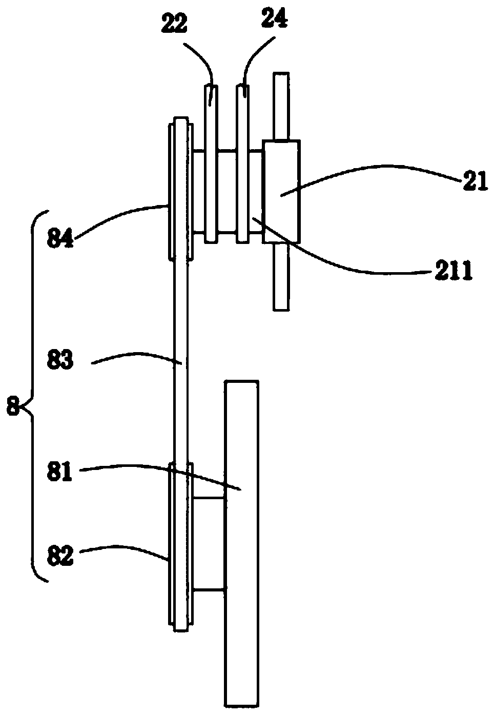
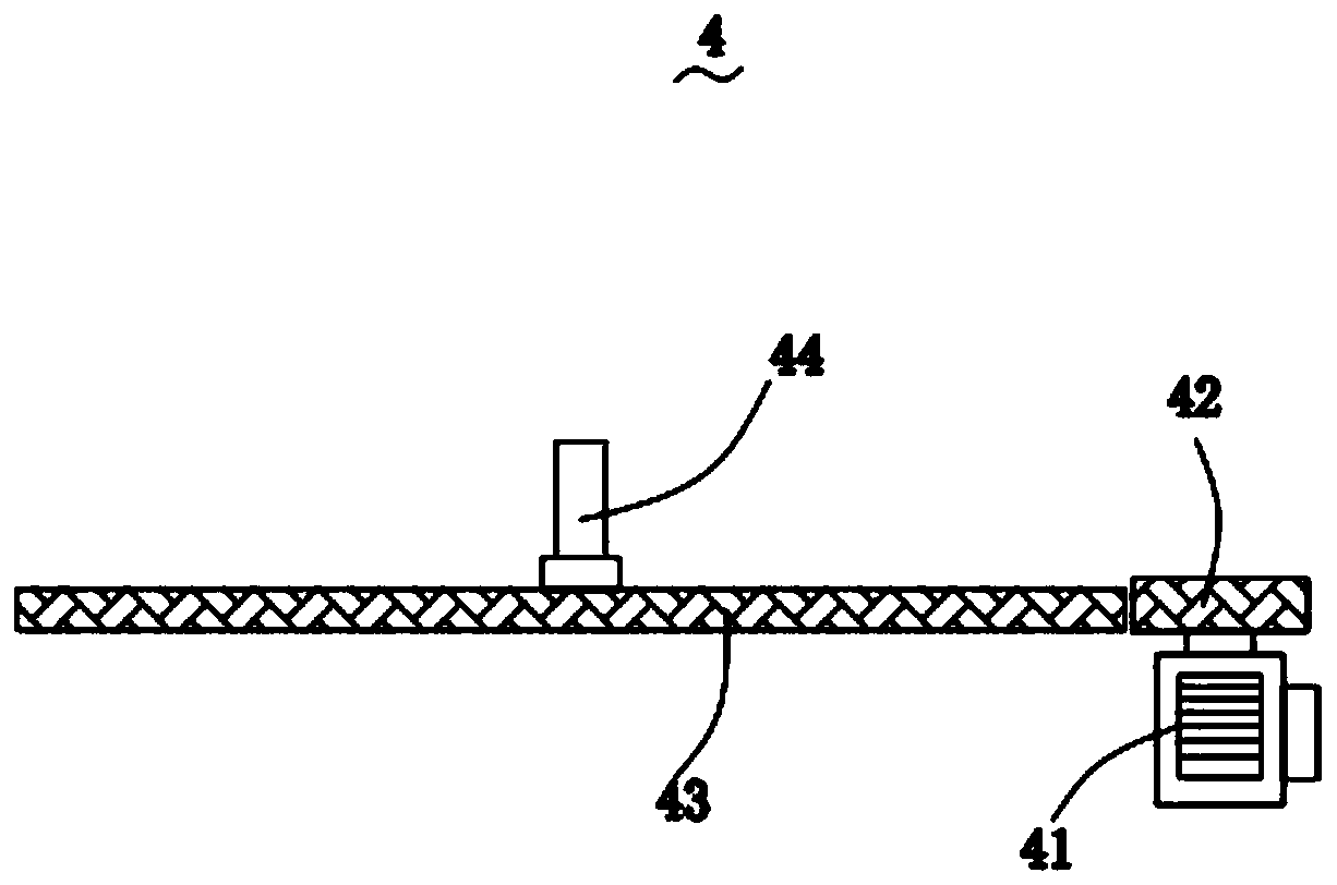
[0028] In order to make the technical means, creative features, goals and effects achieved by the present invention easy to understand, the present invention will be further described below in conjunction with specific embodiments.

[0029] Such as Figure 1-Figure 5 As shown, a corn planter according to the present invention includes a conveying mechanism 1, a stirring mechanism 2, a box body 3, a feeding control mechanism 4, a closing mechanism 5, a discharging mechanism 6, a moving mechanism 7 and a driving mechanism 8; The inner top layer of the conveying mechanism 1 is equipped with the stirring mechanism 2, and the stirring mechanism 2 is connected to the driving mechanism 8 in rotation, and the stirring mechanism 2 is used to speed up the circulation speed; the bottom side wall of the conveying mechanism 1 is provided with There is the box body 3; the inside of the box body 3 is equipped with the blanking control mechanism 4, and the blanking control mechanism 4 is used...


PUM


Abstract

The invention relates to the technical field of agricultural equipment, in particular to a corn planter. The corn planter comprises a conveying mechanism, a stirring mechanism, a box body, an unloading control mechanism, a closing mechanism, discharging mechanisms, a movement mechanism and a driving mechanism. Three stirring wheels distributed in a triangular shape are mounted in a storage box, when a driving wheel rotates, the three stirring wheels can synchronously rotate, so that corn on the top layer and the bottom layer of the storage box can be stirred, the corn circulation speed is greatly increased, and blockage of the corn in the storage box is avoided. Multiple discharging pipes are adopted, the intervals among the discharging pipes can be adjusted to be identical to the requiredplant distance, so that multiple seeds can be discharged each time, the distance between seeds is identical to the plant distance, and accurate and efficient planting is realized; a blocking plate and a discharging port can alternately pass by the bottom of a first circulating pipe, thus, seed discharging can be stopped after one group of seeds are discharged, the required plant distance can be reserved for different groups of seeds, and the planting effect is improved.

Description

technical field [0001] The invention relates to the technical field of agricultural equipment, in particular to a corn seeder. Background technique [0002] Corn seeder refers to a planting machine that uses crop corn seeds as the sowing object. Usually, the name of the seeder is often named after the name of the crop type, such as corn seeder, corn hole seeder, etc. [0003] The current corn seeder can only sow part of the seeds at a time when sowing, which cannot well realize the simultaneous sowing of seeds in different positions, resulting in low sowing efficiency; the stirring of the storage box only exists on the feeding port , and the lack of stirring equipment on the upper layer of the storage box, which in turn leads to a slower feeding speed, still leads to blockage. In view of this, the invention provides a kind of corn planter, and it has the following characteristics: [0004] (1) A kind of corn seeder of the present invention, installs three agitating wheels ...

Claims


Application Information

Patent Timeline
Patent Type & Authority Patents(China)
IPC IPC(8): A01C7/18A01C7/20
CPCA01C7/18A01C7/20
Inventor 许美凤
Owner 许美凤
Learn More