Self-cleaning stop valve

A shut-off valve, self-cleaning technology, applied in cleaning methods and utensils, cleaning methods using tools, lift valves, etc., can solve problems such as leakage, the valve disc cannot be completely closed, and the effect of the shut-off valve is affected.

Inactive Publication Date: 2020-09-25
韩国昊
View PDF0 Cites 5 Cited by
  • Summary
  • Abstract
  • Description
  • Claims
  • Application Information

AI Technical Summary

Problems solved by technology

The existing globe valve often has solid impurities adsorbed on the sealing surface of the valve seat during the opening process of the valve hole. When the valve clack is closed, it will directly press on these impurities, which will cause the valve clack to fail to close completely and cause leakage, which affects the shut-off valve. The use effect will damage the seal in severe cases; and when the valve hole is opened for a long time, the valve disc will always be washed by the medium, which will damage the seal on the valve disc and affect the service life of the globe valve.

Method used


Image

  • Self-cleaning stop valve
  • Self-cleaning stop valve
  • Self-cleaning stop valve

Examples


Embodiment Construction

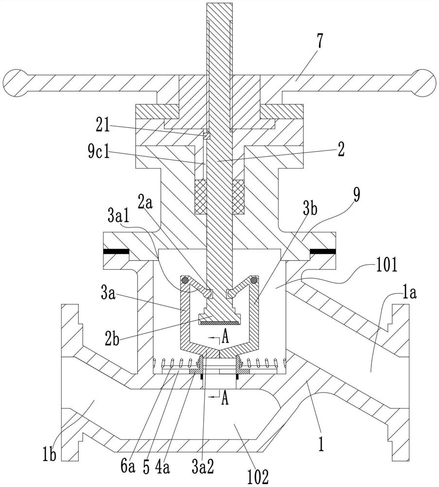
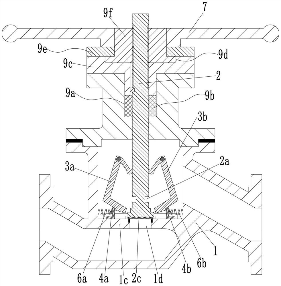
[0021] see Figure 1-7 As shown, a self-cleaning globe valve includes a valve body 1, an upper valve chamber 101 and a lower valve chamber 102 are arranged in the valve body 1, and the valve body 1 is arranged between the upper valve chamber 101 and the lower valve chamber 102. There is a valve plate 1c between them, and the valve plate 1c is provided with a valve hole 1d for connecting the upper valve chamber 101 and the lower valve chamber 102, and the side of the valve body 1 is provided with an outlet pipe 1a communicating with the upper valve chamber 101 , and the inlet pipe 1b communicating with the lower valve cavity 102; the upper opening of the upper valve cavity 101 is fixedly equipped with a valve cover 9, and the valve cover 9 is provided with a valve stem 2 along a direction perpendicular to the valve plate 1c, so The lower end of the valve stem 2 extends into the upper valve cavity 101 and is provided with a valve flap 2b for controlling the on-off of the valve h...


PUM


Abstract

The invention discloses a self-cleaning stop valve. The self-cleaning stop valve comprises a valve body, wherein an upper valve cavity and a lower valve cavity are formed in the valve body; a valve plate is arranged in the valve body; a valve hole is formed in the valve plate; an outlet pipe which is in communication with the upper valve cavity and an inlet pipe which is in communication with thelower valve cavity are arranged on the side face of the valve body; a valve cover is fixedly arranged at an opening in the upper end of the upper valve cavity; a valve rod is arranged in the valve cover; a valve flap is arranged at the lower end of the valve rod; slide rails are arranged on the two sides of a sealing surface at the upper end of the valve hole in the valve plate; a left scraper assembly and a right scraper assembly are symmetrically arranged on the two sides of the valve hole between the two slide rails; a left driving lever and a right driving lever are symmetrically hinged tothe two sides of the valve rod in the upper valve cavity; the upper end of the left driving lever is connected with the valve rod, and the lower end is connected with the left scraper assembly; and the upper end of the right driving lever is connected with the valve rod, and the lower end is connected with the right scraper assembly. The self-cleaning stop valve is simple in structure, and can beused for cleaning the sealing surface at the upper end of the valve hole.

Description

technical field [0001] The invention belongs to the technical field of pipeline valves, and in particular relates to a self-cleaning stop valve. Background technique [0002] Globe valves are often installed on pipelines in petroleum, petrochemical, chemical, metallurgy, electric power and other fields to cut off the fluid medium being transported in the pipeline. A conventional globe valve generally includes a valve body, a valve stem, a valve disc and a handwheel. The lower part of the valve stem is located in the inner cavity of the valve body, and the valve disc is connected to the bottom of the valve stem. The existing globe valve often has solid impurities adsorbed on the sealing surface of the valve seat during the opening process of the valve hole. When the valve clack is closed, it will directly press on these impurities, which will cause the valve clack to fail to close completely and cause leakage, which affects the shut-off valve. The use effect will damage the ...

Claims


Application Information

Patent Timeline
Patent Type & Authority Applications(China)
IPC IPC(8): F16K1/04F16K1/32F16K1/36F16K1/42F16K1/46F16K27/02F16K31/60F16K47/02B08B1/00B08B17/04
CPCB08B1/005B08B1/008B08B17/04F16K1/04F16K1/32F16K1/36F16K1/42F16K1/46F16K27/02F16K31/60F16K47/023
Inventor 韩国昊李红生邵倩倩
Owner 韩国昊
Why Eureka
Try Eureka