Thermodynamic system of back pressure unit transformed into extraction condensing unit and working method

A technology of back pressure unit and thermal system, applied in the direction of machines/engines, mechanical equipment, steam engine devices, etc., can solve problems such as power consumption and replenishment of factory power consumption, so as to increase evaporation and solve the problem of power consumption and replenishment of factory power consumption. , Improve the effect of operating economy

Pending Publication Date: 2020-09-25
XIAN XIRE ENERGY SAVING TECH +1
View PDF0 Cites 5 Cited by
  • Summary
  • Abstract
  • Description
  • Claims
  • Application Information

AI Technical Summary

Problems solved by technology

[0003] The purpose of the present invention is to overcome the above-mentioned shortcomings, and provide a thermal system and working method for transforming a back pressure unit into an extraction unit, which can effectively solve the problem of power consumption and replenishment when the heating load is low

Method used


Image

  • Thermodynamic system of back pressure unit transformed into extraction condensing unit and working method
  • Thermodynamic system of back pressure unit transformed into extraction condensing unit and working method
  • Thermodynamic system of back pressure unit transformed into extraction condensing unit and working method

Examples


Embodiment Construction

[0016] The present invention will be further described below with reference to the accompanying drawings.

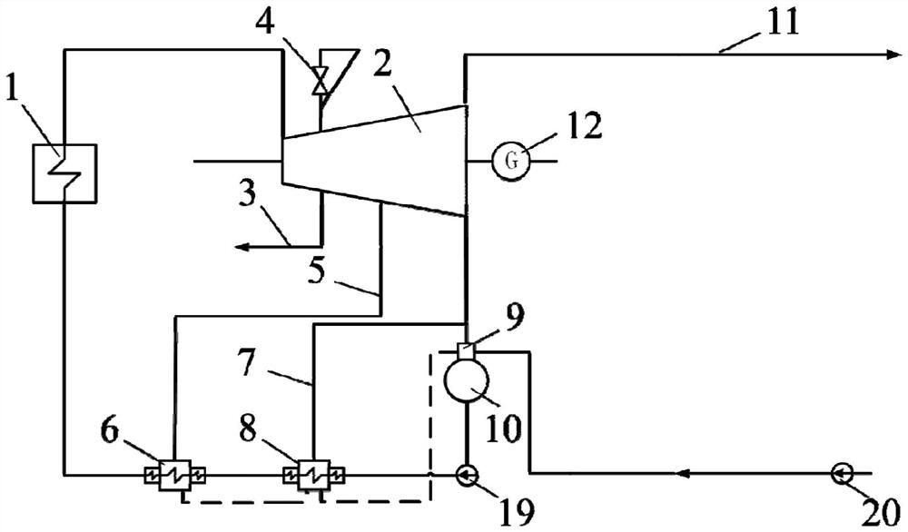
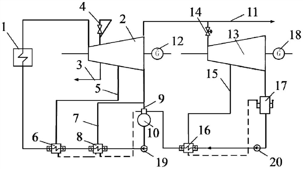
[0017] see figure 2 , the present invention includes a back pressure heat supply steam turbine 2 and a low pressure condensing steam turbine 13, the back pressure heat supply steam turbine 2 is connected to the boiler 1, the steam supply main pipe 11 of the back pressure heat supply steam turbine 2 is connected to the low pressure condensing steam turbine 13, and the low pressure condensing steam turbine The steam supply main pipe 11 of 13 is provided with a flow regulating valve 14 , the back pressure heating steam turbine 2 is connected to the first-stage generator 12 , and the low-pressure condensing steam turbine 13 is connected to the second-stage generator 18 . The pressure heating steam turbine 2 is provided with a medium-pressure extraction steam 3, and a seat cylinder valve 4 through which the pressure of the medium-pressure extraction steam 3 passes is adjuste...


PUM


Abstract

The invention discloses a thermodynamic system of a backpressure unit transformed into an extraction condensing unit and a working method. According to the thermodynamic system, exhaust steam of an original backpressure heat supply steam turbine is utilized, and newly added exhaust steam is used for a low-pressure condensing steam turbine, so that the existing backpressure unit is transformed intothe extraction condensing unit; when the heat supply demand amount is small, the original backpressure heat supply steam turbine can still be kept to admit steam at the designed flow, and the flow ofa steam supply mother pipe of an industrial user is controlled to meet the user demand value by increasing the opening degree of a flow adjusting valve on a pipeline from the exhaust steam of the backpressure heat supply steam turbine to admission steam of the low-pressure condensing steam turbine, and the surplus exhaust steam of the backpressure unit overflows to the low-pressure condensing steam turbine for power generation; and when the heat supply demand mount is large, the evaporation capacity of a boiler can be improved, and meanwhile, the opening degree of the flow adjusting valve onthe pipeline from the exhaust steam of the backpressure heat supply steam turbine to the admission steam of the low-pressure condensing steam turbine is reduced, so that the admission steam of the low-pressure condensing steam turbine is reduced to meet the requirement that the flow of the steam supply mother pipe of the industrial user meets the user demand value.

Description

technical field [0001] The invention belongs to the field of steam turbine power generation, and in particular relates to a thermal system and a working method for transforming a back pressure unit into a condensation extraction unit. Background technique [0002] In order to meet the heating demand of industrial users, a certain number and scale of small back pressure heating units have been put into operation in various regional industrial parks in my country. Limited by various internal and external factors such as the local government's subsidy for equipment utilization hours and other preferential policies, the settled enterprises did not meet the planned expectations, or the construction progress was slow, and other internal and external factors, often there was a discrepancy between the long-term heating plan and the actual situation in the construction area. Large, the heat load is seriously lower than expected. This will cause the back pressure heating unit to fail...

Claims


Application Information

Patent Timeline
IPC IPC(8): F01K11/02F01K17/02F01K7/38F01K13/00
CPCF01K11/02F01K17/02F01K7/38F01K13/00
Inventor 高庆屈杰马汀山居文平石慧薛朝囡
Owner XIAN XIRE ENERGY SAVING TECH
Why Eureka
Try Eureka