
A large steel pipe tower

A technology of steel pipe towers and steel pipes, which is applied in the field of steel pipe towers, can solve the problems of increased stagnation time of steel pipes, corrosion and damage of steel pipe bottoms, and poor sealing performance, and meet the requirements of reducing the level of lifting operators, fast and accurate installation, and protection The effect of not being corroded

Active Publication Date: 2021-10-22
自贡市大西南电力器材制造有限公司
View PDF8 Cites 0 Cited by
  • Summary
  • Abstract
  • Description
  • Claims
  • Application Information

AI Technical Summary

Problems solved by technology

[0007] Due to the limitations of lifting equipment and operating sites, most places can only adopt the method of segmented vertical towers. It is necessary to lift and insert the support steel pipes into the main steel pipes, and then fix them with flanges. When entering the main steel pipe, because the main steel pipe has no guiding effect, it is difficult for the bolt holes of the flange plate on the support steel pipe to correspond to the bolt holes of the flange plate on the main steel pipe. The difficulty of the vertical tower has extremely high requirements on the technical level of the lifting equipment operators, and at the same time, the stagnation time of the supporting steel pipes increases, which has a high safety risk
[0008] The flange has strong fixing strength, but there is a problem of poor sealing. After installation, there are inevitably gaps between the flanges, which cannot be completely sealed, which makes the steel pipe The inside of the rod is easy to seep into water or generate condensed water
In addition, because the base of the steel pipe pole and the top surface of the pile foundation are tightly connected through the flange, the rainwater and condensation water on the inner wall of the steel pipe pole and the bottom of the pipe cannot be removed. life, there is a safety risk of fracture and dumping due to reduced strength

Method used


Image

  • A large steel pipe tower
  • A large steel pipe tower
  • A large steel pipe tower

Examples


Embodiment Construction

[0039] The technical solution of the present invention will be further described in detail below in conjunction with the accompanying drawings, but the protection scope of the present invention is not limited to the following description.

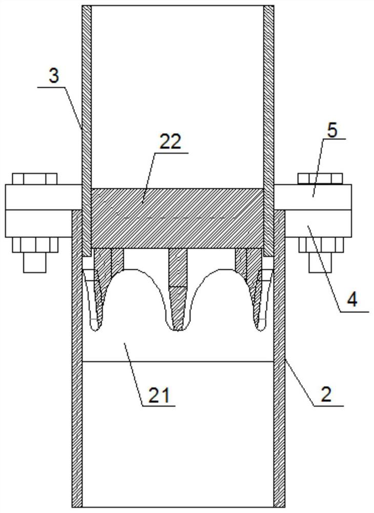
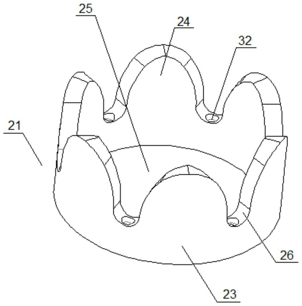
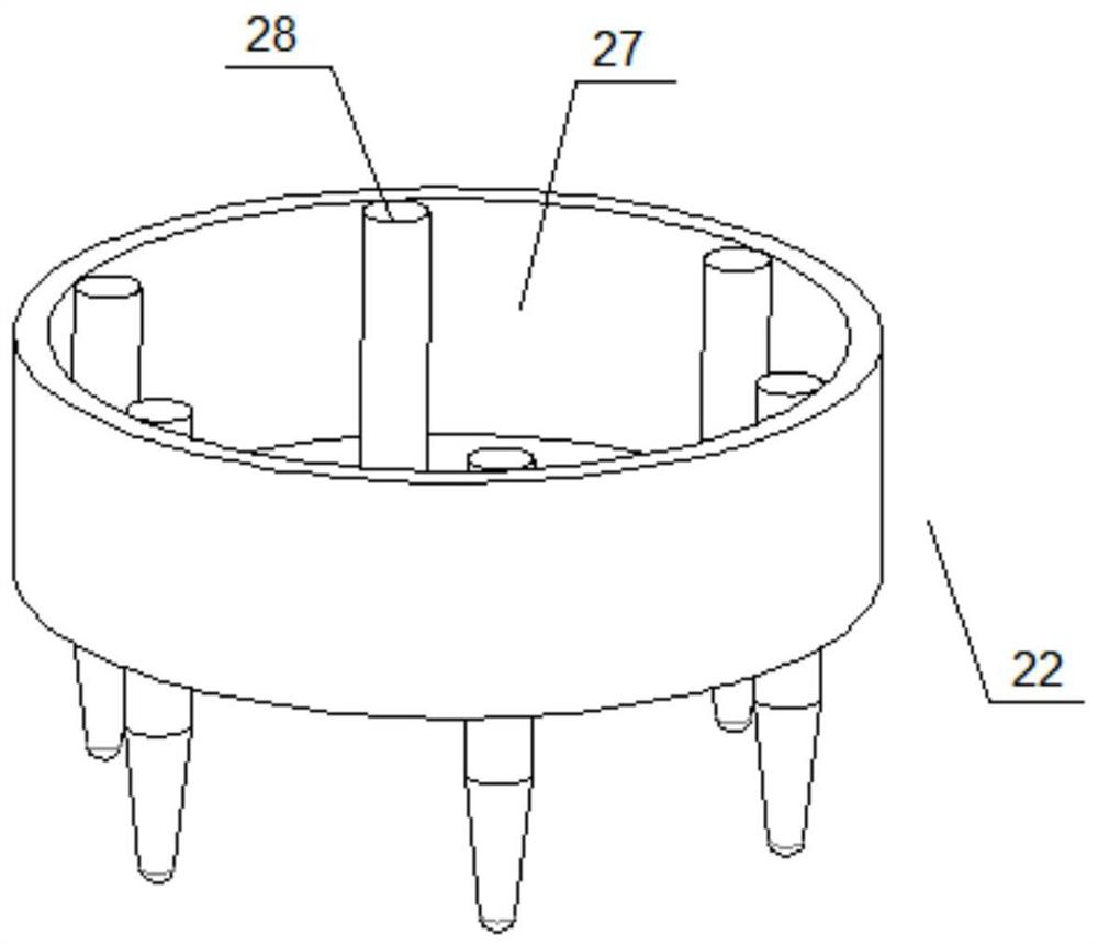
[0040] like Figure 1 to Figure 8 As shown, a large-scale steel pipe tower includes a steel pipe main body 1 and a flange centering assembly, and the steel pipe main body 1 is provided with a flange centering assembly;

[0041] The steel pipe body 1 includes a main steel pipe 2 and a support steel pipe 3, the inner wall of the main steel pipe 2 is provided with a water collecting piece 7, one end of the main steel pipe 2 is fixed with a flange a4, the other end is fixed with a flange base, and one end of the support steel pipe 3 A flange b5 is fixed, and the other end is fixed with a ventilation part 6. A number of bolt holes 8 are opened on the flange a4, and the bolt holes 8 are evenly distributed around the circumference. The structure o...


PUM


Abstract

The invention discloses a large-scale steel pipe tower, which comprises a steel pipe main body and a flange alignment assembly. The flange alignment assembly is arranged inside the steel pipe main body. The centering main part and the centering auxiliary part, the centering main part is fixed on the inner wall of the main steel pipe, and the centering auxiliary part is fixed on the inner wall of the supporting steel pipe. The flange alignment assembly makes the supporting steel pipe rotate in the main steel pipe, so that the bolt holes on flange a correspond to the bolt holes on flange b, thus completing the alignment between flange a and flange b It greatly reduces the difficulty of segmented vertical towers, lowers the requirements for the level of lifting operators, reduces the stagnation time of supporting steel pipes, makes the installation of supporting steel pipes faster and more accurate, and reduces safety risks.

Description

technical field [0001] The invention relates to the field of steel pipe towers, in particular to a large steel pipe tower. Background technique [0002] At present, the plug-in steel pipe tower for power lines is popularized and produced in China because of its beautiful appearance, small footprint, less installation procedures, and high mechanical strength, and it is gradually used to replace traditional angle steel towers and concrete cement poles. The mainstream trend of erecting towers, especially in urban areas, is widely used. However, in the process of actual promotion, installation and use, some problems obviously caused by insufficient design considerations have also been encountered, which have caused certain difficulties for the on-site construction personnel to install and assemble, and need to be improved. [0003] Nowadays, there are many different lifting equipment and different lifting methods in the way of erecting power line towers. However, from the poin...

Claims


Application Information

Patent Timeline
Patent Type & Authority Patents(China)
IPC IPC(8): E04H12/08
CPCE04H12/08
Inventor 屈强
Owner 自贡市大西南电力器材制造有限公司
Learn More