Eureka AIR delivers breakthrough ideas for toughest innovation challenges, trusted by R&D personnel around the world.

Pipe and pond combined type gleaming bioreactor system and microalgae growth carbon consolidating method

A bioreactor and reactor technology, applied in the direction of photobioreactor, bioreactor/fermenter combination, specific-purpose bioreactor/fermenter, etc., can solve the problem of flow resistance reducing the flow speed of algae liquid, etc. Achieve the effect of strengthening the flash effect, improving the distribution of the projection area, and alleviating the light suppression effect

Pending Publication Date: 2020-09-25
ZHEJIANG UNIV
View PDF7 Cites 5 Cited by
  • Summary
  • Abstract
  • Description
  • Claims
  • Application Information

AI Technical Summary

Problems solved by technology

However, the setting of spoiler baffles increases the flow resistance and reduces the flow velocity of the algae liquid, so it is necessary to develop a new reactor structure to increase the flash frequency to promote the growth of microalgae and carbon sequestration.

Method used


Image

  • Pipe and pond combined type gleaming bioreactor system and microalgae growth carbon consolidating method
  • Pipe and pond combined type gleaming bioreactor system and microalgae growth carbon consolidating method

Examples


Embodiment 1

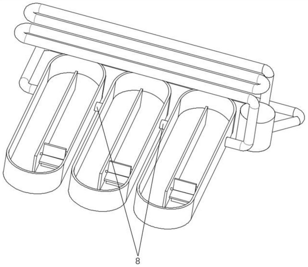
[0035] The tube pool combined flash bioreactor system is composed of the upper horizontal horizontal tube and the lower runway pool, and the horizontal horizontal tube and the runway pool present a cross shape. Arrange 10 rows of horizontal transverse tubes above the length direction of the runway pool, and arrange 3 runway pools below the length direction of the horizontal transverse tubes. The distance between the bottom of the horizontal cross pipe and the bottom of the runway pool is 2 meters. The upper horizontal horizontal tube adopts vertical stacking to form a multi-layer horizontal tube structure, and its tube diameter is 5 cm, and the material is all light-transmitting tubes (that is, polymer tubes with a light transmittance of more than 80%). The total number of layers of horizontal horizontal tubes is 1 layer, and the distance between the walls of two adjacent tubes in the horizontal direction is 10 times the diameter of the tubes. The upper horizontal horizontal ...

Embodiment 2

[0039] The tube pool combined flash bioreactor system is composed of the upper horizontal tube and the lower runway pool, and the horizontal horizontal tube and the runway pool present a cross shape. Arrange 300 rows of horizontal transverse tubes above the length direction of the runway pool, and arrange 6 runway pools below the length direction of the horizontal transverse tubes. The distance between the bottom of the horizontal cross pipe and the bottom of the runway pool is 2 meters. The upper horizontal horizontal tubes are vertically stacked to form a multi-layer horizontal tube structure with a diameter of 5 cm and made of light-transmitting tubes (that is, ordinary glass with a light transmittance of more than 80%). The total number of layers of horizontal horizontal pipes is 2 layers, the distance between the pipe walls of two adjacent pipes in the vertical direction is 1 times the diameter of the pipe, and the distance between the pipe walls of two adjacent pipes in ...

Embodiment 3

[0043] The tube pool combined flash bioreactor system is composed of the upper horizontal tube and the lower runway pool, and the horizontal horizontal tube and the runway pool present a cross shape. Arrange 1000 rows of horizontal transverse tubes above the length direction of the runway pool, and arrange 10 runway pools below the length direction of the horizontal transverse tubes. The distance between the bottom of the horizontal cross pipe and the bottom of the runway pool is 2 meters. The upper horizontal horizontal pipe adopts vertical stacking to form a multi-layer horizontal pipe structure, the diameter of which is 5 cm, and the material is light-transmitting pipe (that is, tempered glass with a light transmittance of more than 80%). The total number of layers of horizontal horizontal pipes is 5 layers, the distance between the pipe walls of two adjacent pipes in the vertical direction is 5 times of the pipe diameter, and the distance between the pipe walls of two adja...


PUM


Abstract

The invention relates to a biomass energy utilization technique, and aims to provide a pipe and pond combined type gleaming bioreactor system and a microalgae growth carbon consolidating method. The system comprises racetrack pond reactors for culturing microalgae, wherein a plurality of horizontal transverse pipes made from a translucent material are arranged above the corresponding racetrack pond reactor in parallel, and are mutually perpendicular to the length direction of the corresponding racetrack pond reactor; the ends of the adjacent horizontal transverse pipes are connected through abent pipe to form a perforated horizontal transverse pipe reactor; an outlet end of the horizontal transverse pipe reactor is sequentially connected with the racetrack pond reactors and a CO2 dissolver through a pipeline, and the outlet end of the CO2 dissolver is sequentially connected with a centrifugal pump and an inlet end of the horizontal transverse pipe reactor through a pipeline; and an air distributor is arranged in the CO2 dissolver and is connected to a CO2 air source through a pipeline. The pipe and pond combined type gleaming bioreactor system can improve the distribution of a light region and a dark region of the surfaces of algae liquid in a racetrack pond, the gleaming effect when microalgae cells flow is notably reinforced, the gleaming frequency when the microalgae cellsmove in the racetrack pond is increased, and promotion of growth and carbon consolidation by microalgae photosynthesis is facilitated.

Description

technical field [0001] The invention relates to biomass energy utilization technology, in particular to a tube-pool combined flash bioreactor system and a method for microalgae growth and carbon fixation. Background technique [0002] Due to their fast growth rate, high light energy utilization efficiency, and high economic value of biomass, microalgae have become CO2 in flue gas. 2 Frontier research hotspots in the fields of emission reduction and new energy development. Make full use of microalgae to capture CO in the flue gas of coal-fired power plants, coal chemical plants, industrial furnaces, etc. 2 , while reducing the cost of raw materials for microalgae production, biomass rich in high-value active ingredients can also be obtained. As the most successful commercial cultivation model in the microalgae cultivation industry, the raceway pond reactor has been widely used at home and abroad because of its simple equipment, process operation and easy scale-up. [0003]...

Claims


Application Information

Patent Timeline
IPC IPC(8): C12M1/24C12M1/04C12M1/02C12M1/00C12N1/12C12N1/20C12R1/89C12R1/01
CPCC12M21/02C12M23/06C12M23/18C12M23/22C12M23/34C12M23/58C12M27/06C12M27/20C12M29/04C12M29/06C12M33/04C12N1/12C12N1/20
Inventor 程军杨卫娟刘建忠岑可法周俊虎王智化张彦威周志军何勇陈沭彤田江磊
Owner ZHEJIANG UNIV
Why Eureka
Eureka Blog
Learn More