Bridge erecting crane auxiliary arm quick installation mechanism

An installation mechanism and installation technology, which can be used in cranes, workpiece clamping devices, hand-held tools, etc., can solve problems such as low efficiency and worker danger.

Active Publication Date: 2020-09-25
滕州潍达智能科技有限公司
View PDF5 Cites 1 Cited by
  • Summary
  • Abstract
  • Description
  • Claims
  • Application Information

AI Technical Summary

Problems solved by technology

[0004] The purpose of the present invention is to solve the shortcomings existing in the prior art, such as: at present, the installation and fixation between the main arm and the auxiliary arm on the crane are mostly carried out manually, which is inefficient and likely to cause danger to workers, and then proposes a Quick Installation Mechanism of Crane Jib for Bridge Installation

Method used


Image

  • Bridge erecting crane auxiliary arm quick installation mechanism
  • Bridge erecting crane auxiliary arm quick installation mechanism
  • Bridge erecting crane auxiliary arm quick installation mechanism

Examples


Embodiment Construction

[0023] The following will clearly and completely describe the technical solutions in the embodiments of the present invention with reference to the accompanying drawings in the embodiments of the present invention. Obviously, the described embodiments are only some, not all, embodiments of the present invention.

[0024] In describing the present invention, it should be understood that the terms "upper", "lower", "front", "rear", "left", "right", "top", "bottom", "inner", " The orientation or positional relationship indicated by "outside", etc. is based on the orientation or positional relationship shown in the drawings, and is only for the convenience of describing the present invention and simplifying the description, rather than indicating or implying that the referred device or element must have a specific orientation, so as to Specific orientation configurations and operations, therefore, are not to be construed as limitations on the invention.

[0025] refer to Figure ...


PUM


Abstract

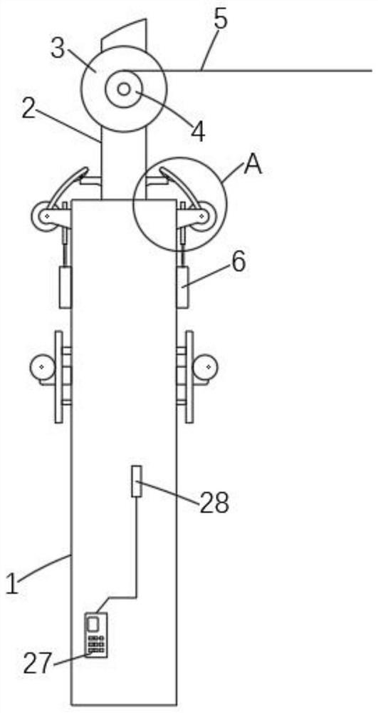
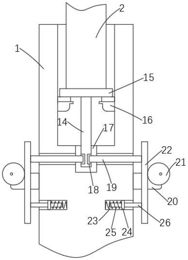
The invention discloses a bridge erecting crane auxiliary arm quick installation mechanism. The bridge erecting crane auxiliary arm quick installation mechanism comprises a main arm and an auxiliary arm. The end of the main arm is provided with a groove for mounting of the auxiliary arm. A traction motor is fixed to the auxiliary arm. A winding wheel is fixed to the outer side of an output shaft of the traction motor. A traction steel rope is wound around the outside of the winding wheel. Two convex blocks are symmetrically mounted outside the auxiliary arm. Abutting assemblies matched with the two convex blocks are symmetrically mounted outside the main arm. A fixed insertion rod is fixed to the end, inserted into the groove, of the auxiliary arm. The inner bottom of the groove is provided with an insertion groove matched with the fixed insertion rod. The outside of the end, far away from the auxiliary arm, of the fixed insertion rod is symmetrically provided with two limiting grooves. Opposite insertion assemblies matched with the two limiting grooves are symmetrically mounted outside the main arm. The bridge erecting crane auxiliary arm quick installation mechanism implements three-time fixation on the auxiliary arm inserted at the end of the main arm in a mechanical driving mode, saves time and labor, improves the opposite insertion installation efficiency, can also preventaccidental injuries to workers and is practical and reliable.

Description

technical field [0001] The invention relates to the technical field of crane jib installation structures, in particular to a crane jib rapid installation mechanism for bridge installation. Background technique [0002] Bridges generally refer to structures erected on rivers, lakes and seas to allow vehicles and pedestrians to pass smoothly. In order to adapt to the modern high-speed development of the transportation industry, bridges are also extended to buildings that cross mountain streams, poor geology or meet other transportation needs to make traffic more convenient. A bridge is generally composed of a superstructure, a substructure, a support and ancillary structures. The superstructure is also called a bridge span structure, which is the main structure for crossing obstacles; the substructure includes abutments, piers and foundations; Or the force transmission device installed at the supporting place of the bridge abutment; the auxiliary structures refer to the bridg...

Claims


Application Information

Patent Timeline
Patent Type & Authority Applications(China)
IPC IPC(8): B25B27/02B25B11/02B66C23/70
CPCB25B11/002B25B11/02B25B27/026B66C23/708
Inventor 韩雪
Owner 滕州潍达智能科技有限公司
Why Eureka
Try Eureka