Gear drilling and chamfering integrated device

A gear and chamfering technology, which is applied in the field of gear drilling and chamfering integrated equipment, can solve the problems of long processing time, increased work intensity, and low processing efficiency.

Pending Publication Date: 2020-09-25
重庆赛之源齿轮制造有限公司
View PDF0 Cites 1 Cited by
  • Summary
  • Abstract
  • Description
  • Claims
  • Application Information

AI Technical Summary

Problems solved by technology

The use of machining centers to drill and chamfer gears has the following disadvantages: 1. The equipment cost is high, and the processing cost is high; 2. It needs to be clamped twice, which increases the work intensity and takes a long time for processing; processing, low processing efficiency

Method used


Image

  • Gear drilling and chamfering integrated device
  • Gear drilling and chamfering integrated device

Examples


Embodiment Construction

[0035] Below in conjunction with accompanying drawing and embodiment the present invention will be further described:

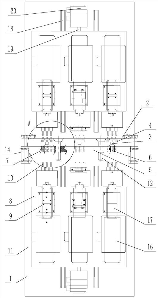
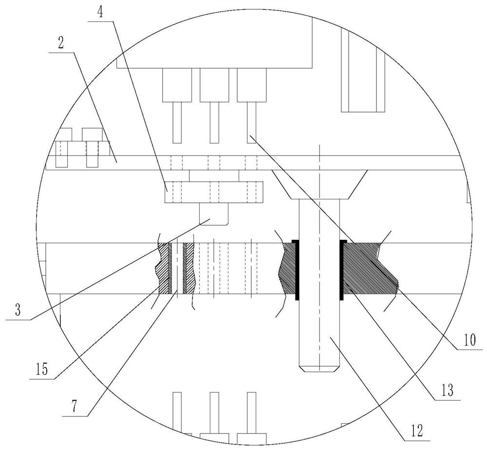
[0036] see figure 1 and figure 2 Shown: gear drilling and chamfering integrated equipment, including a frame body 1, a positioning plate 2 arranged horizontally is arranged on the frame body 1, a mandrel 3 is provided on one side surface of the positioning plate 2, and the gear 4 to be processed can be sleeved On the mandrel 3 and make the end face of the gear stick to support on the surface of the positioning plate; the outer end face of the spaced mandrel is provided with a clamping plate 5, and the clamping plate and the positioning plate are arranged in parallel, and the corresponding mandrel on the clamping plate An insertion hole 6 is provided for inserting the front end of the mandrel; a longitudinal movement control mechanism of the clamping plate is provided between the clamping plate and the positioning plate to drive the clamping plate to move lo...


PUM


Abstract

The invention discloses a gear drilling and chamfering integrated device. The gear drilling and chamfering integrated device comprises a frame body, wherein a positioning plate which is arranged in the transverse direction is fixedly arranged in the longitudinal middle of the upper end of the frame body; a mandrel which is arranged outwards is fixedly connected to the surface of one side of the positioning plate; a gear to be machined can be arranged on the mandrel in a sleeving mode and can be matched with the mandrel; the end face of the gear is attached to and supported on the side face ofthe positioning plate; a clamping plate is arranged on the outer end face of the mandrel in a spaced mode; the clamping plate and the positioning plate are arranged in parallel; an inserting hole allowing the mandrel to be inserted therein is formed in the position, corresponding to the mandrel, of the clamping plate; a clamping plate longitudinal movement control mechanism is arranged between theclamping plate and the positioning plate and is used for driving the clamping plate to move longitudinally, so that the outer end of the mandrel is inserted into the inserting hole, and the clampingplate abuts against and is supported on the outer end face of the gear so as to clamp the gear; and a plurality of pairs of guide holes which are formed at intervals in the circumferential direction of the gear are formed in the positioning plate and the clamping plate in pairs in the left-right direction. The gear drilling and chamfering integrated device has the advantages that drilling and chamfering of the gear can be completed more conveniently, the machining efficiency can be improved, and the working intensity can be reduced.

Description

technical field [0001] The invention belongs to the field of gear processing technology, and in particular relates to gear drilling and chamfering integrated equipment. Background technique [0002] The gear structure usually includes a plurality of through holes uniformly arranged along the circumferential direction of the gear end face and located inside the gear transmission teeth and passing through the axial direction, and the two ends of the through holes usually have chamfered structures. In the existing gear machining, the through holes are mostly drilled by the machining center, and after drilling, the chamfering tool is used for chamfering. However, this only enables chamfering of the upper end of the through hole. This makes it necessary to remove the gear from the jig and turn the end face of the gear to complete the chamfering process on the other end of the through hole. The use of machining centers to drill and chamfer gears has the following disadvantages: ...

Claims


Application Information

Patent Timeline
IPC IPC(8): B23P23/02
CPCB23P23/02
Inventor 刘昌明
Owner 重庆赛之源齿轮制造有限公司
Why Eureka
Try Eureka