
Auxiliary cooling device used under abnormal high temperature and for cold-rolling mill

A technology of cooling device and cold rolling mill, which is applied to the driving device, workpiece cooling device, roll and other directions of metal rolling mill, can solve the problem of thick plate thickness, temperature increase of plate and work roll, and inability to meet the cooling requirements of work roll and plate. Cooling requirements and other issues to achieve the effect of saving energy and reducing costs

Inactive Publication Date: 2020-09-25
刘天芳
View PDF4 Cites 4 Cited by
  • Summary
  • Abstract
  • Description
  • Claims
  • Application Information

AI Technical Summary

Problems solved by technology

[0003] However, during the rolling of the existing cold rolling mills, due to various reasons, such as excessive rolling pressure, thick plate thickness, etc., the temperature of the plate and work rolls will increase abnormally. The cooling circulation system of the mill itself can no longer meet the cooling and cooling requirements of the work rolls and plates, so it is necessary to propose an auxiliary cooling device for the auxiliary high temperature state of the cold rolling mill

Method used


Image

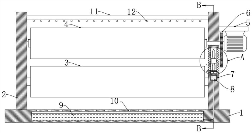
  • Auxiliary cooling device used under abnormal high temperature and for cold-rolling mill
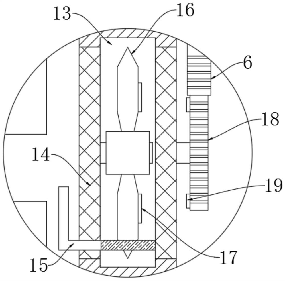
  • Auxiliary cooling device used under abnormal high temperature and for cold-rolling mill
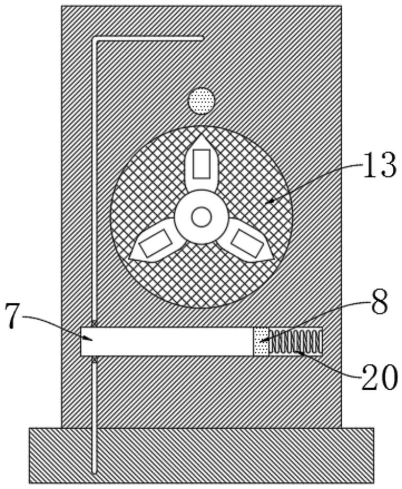
  • Auxiliary cooling device used under abnormal high temperature and for cold-rolling mill

Examples


Embodiment Construction

[0017] The following will clearly and completely describe the technical solutions in the embodiments of the present invention with reference to the accompanying drawings in the embodiments of the present invention. Obviously, the described embodiments are only some, not all, embodiments of the present invention.

[0018] In describing the present invention, it should be understood that the terms "upper", "lower", "front", "rear", "left", "right", "top", "bottom", "inner", " The orientation or positional relationship indicated by "outside", etc. is based on the orientation or positional relationship shown in the drawings, and is only for the convenience of describing the present invention and simplifying the description, rather than indicating or implying that the referred device or element must have a specific orientation, so as to Specific orientation configurations and operations, therefore, are not to be construed as limitations on the invention.

[0019] refer to Figure ...


PUM


Abstract

The invention discloses an auxiliary cooling device used under abnormal high temperature and for a cold-rolling mill. The auxiliary cooling device comprises a base and two stand column plates symmetrically connected to the two sides of the upper end of the base. A work roller is rotationally connected between the side walls of the stand column plates. A load bearing roller is fixedly connected between the side walls of the stand column plates. A motor is fixedly mounted on the side wall of one stand column plate. An output shaft of the motor is coaxially and fixedly connected with the work roller, a main gear is coaxially and fixedly connected to the output shaft of the motor, and round grooves are formed in the side walls of the stand column plates. Through the arrangement of a fan, the main gear, an auxiliary gear, a limiting mechanism, a liquid pumping mechanism, when the work roller and a plate are under abnormal high temperature, the fan can be driven by the motor to rotate, heatradiation air is generated to assisting in heat radiation, meanwhile, cooling liquid can be pumped out to be sprayed to the surfaces of the work roller and the plate, cooling is assisted, the fan cannot rotate under the normal temperature state, energy consumption is reduced, the device conforms to production practice, and energy is reasonably utilized.

Description

technical field [0001] The invention relates to the technical field of cold rolling mills, in particular to an auxiliary cooling device for cold rolling mills at abnormally high temperatures. Background technique [0002] The cold rolling mill is a kind of cold rolling processing equipment for metal materials with high processing precision. The cold rolling mill usually includes two parts: the working mechanism and the transmission mechanism. The working mechanism includes the organic frame, rolls and roll bearings. For load-bearing rollers and when working. When working, the plate passes above the bearing roll, and the plate is rolled by the rotation of the work roll. During the rolling process, due to the deformation of the plate, a large amount of internal energy is released instantly, so the temperature of the work roll and the plate will rise rapidly. , so it is necessary to cool the work rolls and plates in time. [0003] However, during the rolling of the existing c...

Claims


Application Information

Patent Timeline
Patent Type & Authority Applications(China)
IPC IPC(8): B21B27/10B21B45/02B21B35/12
CPCB21B27/10B21B35/12B21B45/0209B21B45/0233B21B2027/103B21B2045/0212
Inventor 刘天芳杨伟
Owner 刘天芳
Learn More