
Permanent magnet motor and compressor and air conditioner with same

A technology of permanent magnet motors and permanent magnets, applied in magnetic circuits, synchronous machines, electromechanical devices, etc., can solve the problems of single sluggish display of permanent magnet motors, reduce the probability of magnetic flux leakage, improve work efficiency, and improve magnetic isolation capabilities Effect

Pending Publication Date: 2020-09-22
ZHUHAI GREE REFRIGERATION TECH CENT OF ENERGY SAVING & ENVIRONMENTAL PROTECTION
View PDF0 Cites 1 Cited by
  • Summary
  • Abstract
  • Description
  • Claims
  • Application Information

AI Technical Summary

Problems solved by technology

[0003] The first object of the present invention is to provide a kind of permanent magnet motor, to solve the problem that the existing permanent magnet motor shows a single sluggishness

Method used


Image

  • Permanent magnet motor and compressor and air conditioner with same
  • Permanent magnet motor and compressor and air conditioner with same
  • Permanent magnet motor and compressor and air conditioner with same

Examples


Embodiment 1

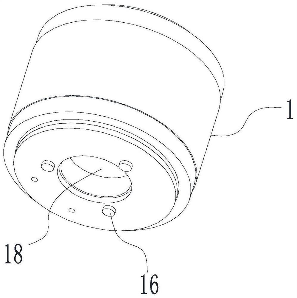
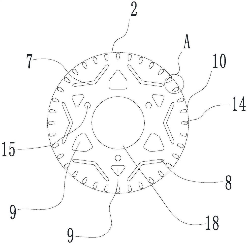
[0036] combined with Figure 1-11 As shown, the present embodiment provides a permanent magnet motor, including a rotor and a stator. The rotor includes components such as a rotor core 1, a squirrel cage 11, and a permanent magnet 4. The stator includes components such as a stator core 19 and a winding 20. The following is The structural features and improvements of the rotor and stator of this embodiment are further described.

[0037] combined with Figure 1-7 As shown, the rotor core 1 of this embodiment is composed of three segmented iron cores, that is, the first iron core 2 and two second iron cores 3 in the figure, and the two second iron cores 3 are respectively located at the ends of the first iron core 2 Both ends, and the three are coaxially arranged, and the first iron core 2 and the middle part of the second iron core 3 are provided with a shaft hole 18 through which the power supply shaft 27 passes. The first iron core 2 and the second iron core of this embodime...

Embodiment 2

[0050] combined with Figure 12 As shown, this embodiment provides a compressor, which includes a body 26, a motor stator assembly cylinder 28, a motor balance weight 29 and the permanent magnet motor described in the above embodiment, the permanent magnet motor is installed in the body 26, and The stator of the permanent magnet motor is installed on the stator assembly cylinder. Other structures of the permanent magnet motor have been given in the above-mentioned embodiments, so this embodiment will not repeat them, and the rest of the structure of the compressor is the same as the prior art, so this implementation The example does not describe other components of the compressor, but those skilled in the art can fully understand its structure and principle.


PUM


Abstract

The invention discloses a permanent magnet motor and a compressor and an air conditioner with the same. The permanent magnet motor comprises a rotor iron core and a stator iron core, a plurality of permanent magnet grooves are formed in the rotor iron core in the circumferential direction of the rotor iron core, a plurality of permanent magnets are installed in the permanent magnet grooves in a one-to-one correspondence mode, and on the radial section of the rotor iron core, at least one end of the two opposite ends of each permanent magnet groove is communicated with a first magnetism isolation bridge hole. According to the permanent magnet synchronous motor, one end or two ends of the permanent magnet groove are communicated with the first magnetic isolation bridge holes, so that the magnetic isolation capability of the permanent magnet synchronous motor is improved, the magnetic leakage probability is reduced, and the working efficiency of the permanent magnet motor is improved.

Description

technical field [0001] The invention relates to the technical field of motors, in particular to a permanent magnet motor and a compressor and an air conditioner having the permanent magnet motor. Background technique [0002] Permanent magnet synchronous motor refers to a kind of synchronous motor whose rotor uses permanent magnets instead of winding wires. It has the advantages of high power factor, constant speed, small size, light weight and high efficiency, and has broad application prospects. However, the existing permanent magnet synchronous motor is prone to magnetic flux leakage, which affects the working efficiency of the motor, and further optimization of the structure of the permanent magnet motor is required. Contents of the invention [0003] The first object of the present invention is to provide a permanent magnet motor to solve the problem of single sluggishness of the existing permanent magnet motor. [0004] In order to achieve the above object, the tech...

Claims


Application Information

Patent Timeline
Patent Type & Authority Applications(China)
IPC IPC(8): H02K21/02H02K21/46H02K1/27H02K1/14H02K3/34
CPCH02K1/14H02K1/2706H02K3/345H02K21/021H02K21/46
Inventor 陈世国朱红伟刘靖王伟
Owner ZHUHAI GREE REFRIGERATION TECH CENT OF ENERGY SAVING & ENVIRONMENTAL PROTECTION
Learn More