
Drainage solenoid valve, fuel cell cold start system and cold start method

A solenoid valve and cold start technology, applied in the direction of fuel cells, circuits, valve details, etc., can solve the problems of increasing system complexity, cost parasitic power and start time, affecting system cold start performance, heating PTC power is small, etc., to achieve Reduce cold start time, reduce ice breaking time, and reduce the effect of parasitic power

Active Publication Date: 2020-09-22
TONGJI UNIV
View PDF7 Cites 5 Cited by
  • Summary
  • Abstract
  • Description
  • Claims
  • Application Information

AI Technical Summary

Problems solved by technology

[0003] In order to prevent the solenoid valve from freezing due to condensation at low temperatures after the system stops and affect the cold start performance of the system, most of the current methods are to increase the heating PTC (PTC ceramic heating element) through the solenoid valve, and start heating the PTC before the system is cold started. After judging that the temperature of the solenoid valve exceeds the set threshold, the system is starting at low temperature; the heating power of the PTC is small, and the heating time is long; this technology increases the complexity, cost, parasitic power and start-up time of the system

Method used


Image

  • Drainage solenoid valve, fuel cell cold start system and cold start method
  • Drainage solenoid valve, fuel cell cold start system and cold start method
  • Drainage solenoid valve, fuel cell cold start system and cold start method

Examples


Embodiment 1

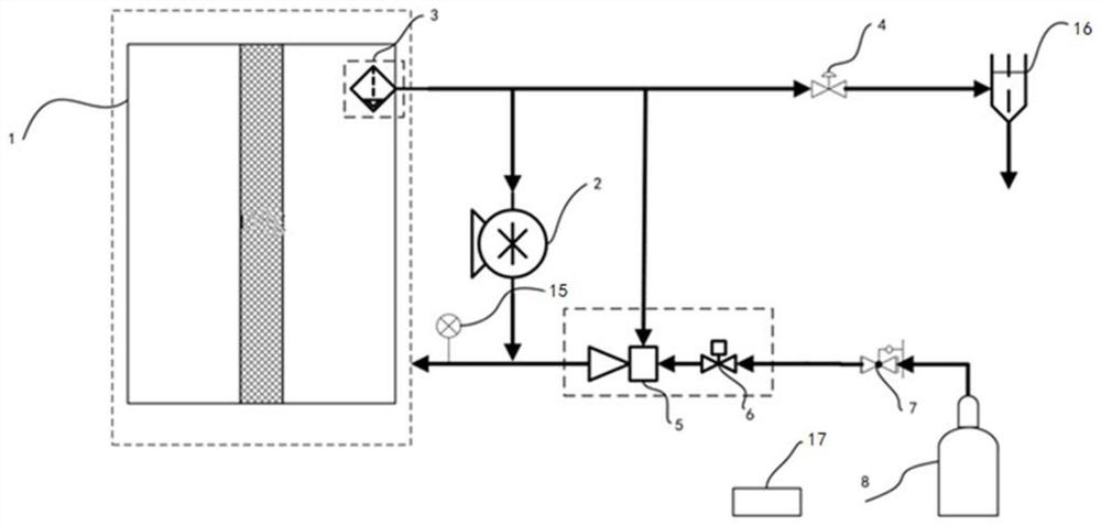
[0035] This embodiment provides a drain solenoid valve, a fuel cell cold start system and a cold start method.

[0036] Drain solenoid valve:

[0037] It includes a valve seat 9, a valve stem 10 and an electromagnetic coil 11. The electromagnetic coil 11 moves the valve stem 10 by energizing and de-energizing. The valve stem 10 and the electromagnetic coil 11 are installed on the valve seat 9, and the valve seat 9 forms a fluid inlet channel 13 and A diaphragm 12 is arranged between the fluid discharge passage 14, the fluid entry passage 13, the fluid discharge passage 14 and the valve stem 10, and the diaphragm 12 prevents the fluid from entering the passage 13 and the fluid discharge passage 14 from entering the valve stem 10 and the valve stem. The sliding gap formed between the seats 9. The fluid inlet flow channel 13 and the fluid discharge flow channel 14 are flush with the valve stem 10 , the diaphragm 12 is arranged on the flow channel contact surface of the valve ste...

Embodiment 2

[0046] The diaphragm 12 is connected with the valve seat 9, and the movement of the valve stem 10 makes the diaphragm 12 tense or loosen. All the other are identical with embodiment 1.


PUM

PropertyMeasurementUnit
poweraaaaaaaaaa

Abstract

The invention relates to a drainage solenoid valve, a fuel cell cold start system and a cold start method. The drainage solenoid valve is characterized in that diaphragms are arranged between a fluidinlet runner and a fluid outlet runner of the drainage solenoid valve and a valve rod, and the diaphragms prevent fluid of the fluid inlet runner and the fluid outlet runner from entering a sliding gap formed between the valve rod and a valve seat. The cold start system comprises a hydrogen cylinder, a pressure reducer, a proportional valve, an ejector, a pressure sensor, a galvanic pile, a hydrogen circulating pump, a water segregator, an exhaust pipe and a controller. The cold start method comprises the steps that 1, the controller judges whether the fuel cell is below 0 DEG C or not, and ifyes, the step S2 is executed; and 2, the controller opens the drainage solenoid valve and periodically adjusts the pressure of hydrogen entering the galvanic pile, the controller records the pressurechange period T of the pressure sensor, and whether cold start is carried out or not is judged through judging the period T. Compared with the prior art, the cost is reduced, the complexity is reduced, and the cold start time is shortened.

Description

technical field [0001] The invention relates to the field of fuel cells, in particular to a drain solenoid valve, a fuel cell cold start system and a cold start method. Background technique [0002] A fuel cell is a power generation device that directly converts the chemical energy of fuel into electrical energy. The fuel cell system has high energy conversion efficiency and is an ideal energy utilization method. There is a broad prospect for commercial application. In practice, for an anode closed loop system, in order to avoid anode flooding, it is necessary to drain the anode liquid water regularly, usually using a drain solenoid valve to periodically drain the liquid water. [0003] In order to prevent the solenoid valve from freezing due to condensation at low temperatures after the system stops and affect the cold start performance of the system, most of the current methods are to increase the heating PTC (PTC ceramic heating element) through the solenoid valve, and st...

Claims


Application Information

Patent Timeline
Patent Type & Authority Applications(China)
IPC IPC(8): F16K31/06F16K7/12H01M8/04223H01M8/0438
CPCF16K7/12F16K31/0672H01M8/04253H01M8/04268H01M8/04425Y02E60/50Y02P70/50
Inventor 马天才朱东王凯
Owner TONGJI UNIV
Learn More